|
|
Post by ms on Feb 17, 2023 13:24:19 GMT -5
The field of a permanent magnet is not a function of the material's permeability. Permeability is a term relating to applied magnetic fields. Each region in a magnet makes a field and and is potentially influenced by the fields of all other regions, the same nasty "self-consistent" problem you often have. If the material is not permeable, such as almost holds true for neodymium, then there is no significant effect. Alnico is permeable, and so the effects of "applied magnetic fields" from region to region must be accounted for. |
|
|
|
Post by ms on Feb 16, 2023 13:52:00 GMT -5
The distances are given in mm, so I converted to Tesla and m then the result back to Gauss. If I set Br as 3000 I get exactly the table numbers. How are you handling mm if you use Gauss? All I did was check another source for Br of Alnico5. It gave the same number (12700 G) after converting from mT. That is why I think AK is right. Maybe both the other source and AK are wrong, but in any case, the field strength of strat pole pieces is well known, and there is no need to compute from Br. Edit: A couple more things: 1. The equation consists of Br times a unites factor. You have distance/distance, and so distance units do not matter, but all must be the same. 2. I believe this equation is for uniform magnetization. Alnico has sufficient permeability so that this is not completely correct, and you need a self-consistent solution. Exact agreement might be accidental. |
|
|
|
Post by ms on Feb 16, 2023 13:27:27 GMT -5
Again, no need for the attitude. I made no such assumptions. I took the measurement for Br and applied it to the formula for calculating field force at a distance from the center of the pole of a cylinder magnet: B(x) = {\frac {B\scriptstyle{ r }} 2} [ {\frac {L+X}{\sqrt{ R^2 + (L+X)^2}} } - { \frac x {\sqrt{ R^2 + x^2}} } ]
Seems I made a typo with X and x. Doesn't seem I can edit. This is all you wrote: ==>What do we know about average magnetization of strat pole pieces? This page suggests 12700, which seems very wrong; I think is right if the units are Gauss. |
|
|
|
Post by ms on Feb 16, 2023 11:46:05 GMT -5
==> This still does not explain why that would be true. I want to be able to explain this in terms of the theory.
The basic idea of a permeable material is that the atomic dipoles, or at least larger regions made up of such dipoles, have a tendency to line up with an applied field. But this is a self consistent problem: the field that affects a given region is the applied field and the field generated by the aligment of neighboring regions. This can happen much more easily in a direction through the material that is long rather than short (more regions to affect other regions). So magnetization is much stronger along the string than across it. The applied field from the pole along the string has opposite directions on opposite sides of the pole. Therefore the magnetization must be opposite on the two sides. Thus this longitudinal magnetization must pass through zero over the pole. Exact solution must be numerical, and measurements are not trivial.
|
|
|
|
Post by ms on Feb 16, 2023 11:31:42 GMT -5
Apparently you still have not realized the columns on the left of AK's table are properties of the material, not of specific magnets made from the material. Br (residual induction) is 12700 G for Alnico 5. What reason do you have for thinking it is too high? Well, none, you thought it was a measurement of a magnet, not a property of the material, only indirectly related to a measurement on a specific magnet. You want the math? Not going to work if you are unwilling even to look up the meaning of a column heading and try to understand how that fits into an understanding of a mathematical description of magnetic material properties.
|
|
|
|
Post by ms on Feb 16, 2023 6:10:13 GMT -5
That table on AK's web page suggests that you have about 1000 gauss 1 mm from the pole piece of a strat pickup. When I put the probe against the pole piece from some random strat pickup, I get just under 1000 Gauss on the end pole pieces and a couple hundred less on the others. Why are you wasting people's time with stupid questions like this when it is so easy to get a meter and see for yourself? If you do not understand the theory, a little hands on experience helps.
|
|
|
|
Post by ms on Feb 15, 2023 17:33:09 GMT -5
If we think that the magnet is only there to magnetize the string (and can be removed), why do we think that different magnet types matter? The permanent magnet can be moved to a different place, giving information about the string magnetization. I do not think anybody said it could be removed, as in taken away altogether. Magnets can be permeable and conductive, and thus contribute to the properties of the pickup electrical circuit as well. And of course in their role in magnetizing the string magnets of different strengths affect the vibration of the string in different ways. Do you now agree with our model of string magnetization? |
|
|
|
Post by ms on Feb 14, 2023 14:36:21 GMT -5
but the thing that makes the reluctance model appealing is that it automatically accounts for the contribution of the permeable core in the pickup, since you're looking at all the permeable elements at once, and how the sum reluctance between them changes when the guitar string is moving. I think that including the permeable core in the calculation of the reluctance difference is important and not easy. |
|
|
|
Post by ms on Feb 14, 2023 14:29:20 GMT -5
==> I think the answer is that Flux-max = Flux-saturation * Effective-area.
This equation does not imply that a small cross section means easy saturation.
==> How do you figure? It means exactly that.
On the left side we have flux; it must also be so on the right, and so Flux-saturation is a flux density, giving flux when multiplied by an area. So all this equation says is that the maximum flux through an area is found by multiplying the maximum flux density by the area.
==> Magnetic flux is famously difficult to shield, which is what "removing some of the flux" would amount to.
"Magnetic flux is famously difficult to shield" means that reducing the magnetic field to near zero is difficult. "Removing some of the flux" with high permeability material is easy.
Are there not more important things to discuss? For example, you are claiming that the model of consisting of longitudinal magnetization in the string which changes sign as it crosses the pole piece, producing a radial field, is wrong. Can you show some theoretical or experimental evidence for this?
|
|
|
|
Post by ms on Feb 14, 2023 10:18:48 GMT -5
|
|
|
|
Post by ms on Feb 14, 2023 10:09:27 GMT -5
==> I think the answer is that Flux-max = Flux-saturation * Effective-area.
This equation does not imply that a small cross section means easy saturation.
longitudinal magnetization:
I believe that aquin43 mentioned this above:
Remove the magnetization from the pole piece. Use a magnet* to magnetize from the side, that is, along the face of the pickup. The pickup works (good output) even though the permanent field does not point through the coil along the pole piece. Thus it works as we have described. If you do not want to remove a pickup magnet, you can reduce the output from one of the E strings by locating a magnet as described with the polarity selected to partially cancel the longitudinal magnetization caused by the pickup magnet.
* You need to use a magnet that could be used as a pole piece (such as an actual Fender type alnico pole piece magnet) in order to get the correct spatial field variation.
|
|
|
|
Post by ms on Feb 14, 2023 7:40:13 GMT -5
The magnetization of a long thin piece of permeable material is almost completely along it. In pickup, the component of permanent field along the pole axis does very little. The string is magnetized by the horizontal component (field bends over), which maximizes away from the center.
The component of time varying field in the direction through the coil results from the change in direction of the longitudinal magnetization.
|
|
|
|
Post by ms on Feb 14, 2023 6:04:58 GMT -5
So if the guitar string is always saturated, the reluctance model cannot explain things? The math above seems to suggest that with any normal pickup magnet, the strings are always saturated (as claimed by multiple articles). Also, if the permeable character of the string is changing, how could the change in flux consistently correspond to the velocity? As the string gets closer/further from the magnet, the rate of change of ɸ would increase/decrease, creating inconsistencies in the frequency produced from string velocity. That we demonstrably can achieve a consistent resolved frequency from a guitar string would seem to serve as evidence that this is not happening. The guitar string is not saturated right over the center of the pole piece and for some distance near the center. The direction of longitudinal magnetization changes as its magnitude passes through zero. The details and how they change as a function string position are complicated. Who said the induced voltage is exactly proportional to string velocity? It is actually significantly non-linear, (product of more than one factor) as aquin43 explained above. "Proportional to velocity" is just a good approximation. Antigua: The air gap between the string and the pole piece is a small part of the total air gap around the path of varying flux. The gap is so large that the main purpose of the variable reluctance method, simple solution for certain simple problems, does not apply. One of the conditions for a simple solution is that the air gap in the nearly complete path of permeable material must be small enough so that the fringing field (lines curving outward at the edges of the gap) is small. In the case of a pickup, the fringing field dominates, and other methods of solution are better. |
|
|
|
Post by ms on Feb 13, 2023 17:39:45 GMT -5
What is the source of the reluctance in question, then? It seems to me that the string remaining saturated is essential to the frequency creating a uniform signal, because once saturated dɸ depends only on string velocity (velocity of a constant flux). If ɸ is changing (not at saturation) then dɸ is flux-change-dependent velocity. In other words, if we can assume the string reaches saturation, we don't need to concern ourselves with the string's flux magnitude. Is the reluctance model stated formally somewhere? In the variable reluctance description, the reluctance around some path composed of permeable material changes when the position of a permeable object changes. For example, if we cut a slot in the cross section of a permeable toroid and move magnetic material in and out of the slot, the flux around the toroid changes, assuming, for example, a coil with current drives the flux, or maybe a permanent magnet. The magnetization in the moving magnetic material varies. If this moving magnetic material is saturated, then there still might be some change in the flux around the path, but this would be very subtle and I do not see how you could attribute to variable reluctance. |
|
|
|
Post by ms on Feb 13, 2023 7:37:05 GMT -5
This article seems quite good on the question of the magnetic component of guitar strings: www.gitec-forum-eng.de/wp-content/uploads/2020/08/poteg-3-string-magnetics.pdf. If I'm understanding the reluctance model, it is premised on the string reaching flux saturation such that it is no longer effectively permeable. The article suggests that due to tension-based construction requirements, very little variability is possible in steel grade and content. It also concludes that the saturation point for common strings is around 1.5T (15,000 Gauss). How could strings ever reach saturation if the strongest magnets in pickups are usually not even 1200 Gauss (.12T)? >> Edit I think the answer is that Flux-max = Flux-saturation * Effective-area. For High E that would mean .229mm diameter, which gives about 0.062µT (.0006 Gauss). So even with a high saturation point, the effective area is so tiny that it takes almost nothing to saturate.
The string saturates because it is made from a ferromagnetic material, and therefore has a permeability significantly higher than one. That is, the string in effect "amplifies" the field so that a relatively small applied field increases to a large value inside the string. The reluctance model does not depend on string saturation. As the reluctance varies, so does the magnetization of the string. This could result in the string going in and out of saturation, but the model works for weak fields with no saturation. |
|
|
|
Post by ms on Feb 8, 2023 6:52:22 GMT -5
I was hoping you would do a simulation. Thanks. Circuits using mutually coupled inductors, especially when more than one k is involved, are difficult to understand. The skin effect, creating variable frequency resistors, makes more complication. Here we have a circuit where an aspect of the response is simple. It ought to be good for something.
|
|
|
|
Post by ms on Feb 6, 2023 13:17:21 GMT -5
But it is not just that "it appears more inductive than it should be"; its inductive reactance at all frequencies is that of the low frequency inductance of the normal method (straight line on log log scale where the measurement is good). Here is the Fitler'tron with the new method:  and the original method: 
The inductive reactance at all frequencies is also that expected from the low frequency inductance of the normal measurement. The real part is even more reduced than that of the SDSH1N, approaching the low frequency value. |
|
|
|
Post by ms on Feb 6, 2023 7:19:53 GMT -5
I think that the reason for the disagreement with the other measurement method is a phase problem at higher frequencies. The calculation assumes that the induced voltage leads the current through the exciter by 90 degrees. The field seen by the coil, however, is the combination of the exciter field and the re-radiated field of the pickup losses. The phase of this combined field lags behind the assumed 90 degree lead so that when you calculate the impedance it appears more inductive than it should be. This phase error in the calculation rotates part of the resistive component into the inductive.
I think you are saying that there are differences in the eddy current losses between the two different methods of excitation. Maybe it works like this: when you excite by putting a voltage across the coil, eddy currents are induced in metal pieces by the B field made by the resulting current in the coil. When excite with a B field, eddy currents are also induced in the metal pieces directly by this field. I think that this has consequences for analyzing what the field from the vibrating string does. There are a couple of ways to proceed experimentally. First, increase the eddy current losses by using a cover. I have some brass covers on order, but it appears that they are coming from China; I did not realize this when I made the order. Also, I have a higher loss pickup (Filter'tron, or however that should be written) that I have started to measure. |
|
|
|
Post by ms on Feb 5, 2023 12:25:00 GMT -5
Shown below is a measurement made with the alternate geometry shown in the lower panel from the previous post. The most striking difference between it and the "normal" measurement (shown further down) is that the imaginary part (the inductive reactance) does not bend over, but stays straight, up to the frequency where the measurement goes bad. Also the real (resistive) part is not as large. Why?   |
|
|
|
Post by ms on Feb 5, 2023 11:22:31 GMT -5
What I want is an independent method of measuring changes in frequency, that is, decreasing inductance and increasing resistance as a result of eddy currents. Results from the new method are not what I expected, but first let's look at how it works, and then the results later. The top panel of the figure below shows my normal method of measuring impedance. An ac voltage source drives the series combination of the pickup and a sense resistor (about 1K). Input 1 (to the recording interface) measures the voltage across this series combination, and input 2 measures the voltage across the sensing resistor, which gives the current. The ratio is the impedance through the series combination. A simplified model of a pickup is drawn inside the pickup box. In order to examine the details of L and R, it is necessary to "unparallel" the impedance of the C. This works fine, but it would be nice to have a method which removes the effect of the C in a different way. 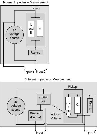
The bottom panel of the figure shows such a different method. An exciter coil is used to induce a voltage in the pickup coil. The voltage is induced around each turn, but of course using Thevenin's theorem, this becomes a single series voltage source. The exciter coil has an Rsense (165 ohms, value not critical, but needs to be known). The exciter coil is as described by Ken Wiltmont. Using the sense resistor is the easiest way to get accurate current information, both amplitude and phase. As usual, input 1 is used as a reference in a cross-spectral measurement with input 2. Rsense (input 2) is about 1K. This is small enough so that the input C of the recording interface and the C of the pickup have little effect. If we knew the value of that little voltage source, we would have a simple impedance measurement, similar to above. However, only the L and R would matter. Actually we only know the voltage to within a constant, and a 90 degree phase shift from the differentiation of the law of magnetic induction. The constant can be found by a calibration at low frequencies, where R can be measured by an ohm meter and the impedance of L is small. So that is a simple view of how it works; results later. |
|
|
|
Post by ms on Jan 6, 2023 9:44:15 GMT -5
Some thing appears to be wrong with what I have done, and so I have removed the explanation. I will work on it some more! OK, I had some connection issues with my equipment, and I was puzzled that my "Christmas present" recording interface has more than twice as much input C on insdtrtument channel 1 as on 2. (That is just the way it is since the switching on the two channels is different. So I am putting back this explanation. 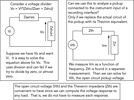 Also, here is an example of what you can do with both kinds of measurements used together:  |
|
|
|
Post by ms on Jan 4, 2023 18:42:52 GMT -5
Let's begin with the following plot: 
The red line is the voltage measured with an exciter coil with the pickup connected directly to the input of a recording interface with an input resistance of 1 M and a capacitance of 160 pf. The blue line is a computed approximation of the open circuit response. It requires as inputs the loaded measurement, the input impedance, and the pickup impedance. Notice that the peak frequency of the computed response is slightly higher than that of the measurement in the current discussion on string based exciter coils, which was made with a preamp with a lower capacitance than the interface (but not zero, of course). I will describe how the computation is accomplished in the next post, using Thevenin's theorem (https://en.wikipedia.org/wiki/Thévenin%27s_theorem), with the extension to ac circuits. This theorem says that a circuit composed of an arbitrary number of impedance elements, as well as voltage and current sources, can be replaced by an equivalent circuit with a single impedance in series with a single voltage source. The impedance is found by setting the voltages sources to zero, but leaving them in place as shorts, and removing the current sources. The impedance between the two terminals is then found. Thus, this impedance is the pickup impedance we measure. However, we do not have the open circuit voltage, but rather a voltage measured into a load, all be it a fairly high impedance, but not infinite. The problem then is to find the open circuit voltage (as a function of frequency) from the load voltage and the impedance. This is not hard, but is left for the next post. |
|
|
|
Post by ms on Jan 3, 2023 20:14:22 GMT -5
The toothpick coil has about 8 db less output than the string coil, still good. The tooth pick diameter is a bit more than twice that of the string. Not sure how that affects the field outside the solenoid.
|
|
|
|
Post by ms on Jan 3, 2023 10:37:49 GMT -5
This is a cool idea. Could it will model eddy currents in metal covers more effectively by having the magnetic lines intersect with the metal cover more like a real guitar string? Some portion of eddy currents are due to the cover, and some the pole pieces, maybe this configuration will place blame more accurately that an exciter that is focused more directly at the pole piece. Even if the string causes its own eddy currents, isn't that a realistic fact of what would happen with moving guitar strings? Maybe a toothpick could be used to avoid eddy currents if string eddy currents don't belong in the measurement, but guitar strings aren't made of wood. A big upside also seems to be that the pickup will magnetically couple with the steal string the way a real pickup would, and that might give a more true output measurement comparison between steel pole pieces versus AlNiCo, and other pole piece configurations, as compared to an air core exciter. Yes, that is what am thinking about a conductive cover like brass. Currents induced in the cover by the time varying field from the string reduce the pickup output. If the field is not right, the loss could be wrong. I do not know how big the effect is, but I think it cannot hurt to get it right, or at least close. The eddy currents in the string that I am concerned about result from the current in the coil around it. This is different from anything that might get induced by the string vibration. Your final point is subtle; I do not know if that makes a difference, but it is something to think about. |
|
|
|
Post by ms on Jan 2, 2023 17:29:09 GMT -5
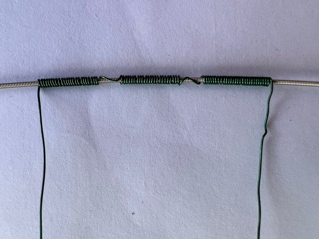
The purpose of the exciter coil described in this discussion is to make a magnetic field very similar in shape to that produced by the strong. This would, for example, excite a similar pattern of currents in the metal parts of a guitar pickup. When a guitar string is magnetized, it is like two long thin bar magnets along the string with like poles facing each other over the pickup pole piece. The vibrating string changes the flux from these magnets through the pickup coil. This driver coil uses a section of a string as a core magnetized by coils to simulate this field. Below is a photo of a coil setup for driving a pair of humbucker poles. The winding direction changes on opposite sides of a pole gap. The string has a dimeter of .042". The wrap is nickel, which has a permeability similar to carbon steel
 The coil is glued into a plastic (3D printed PLA) holder. 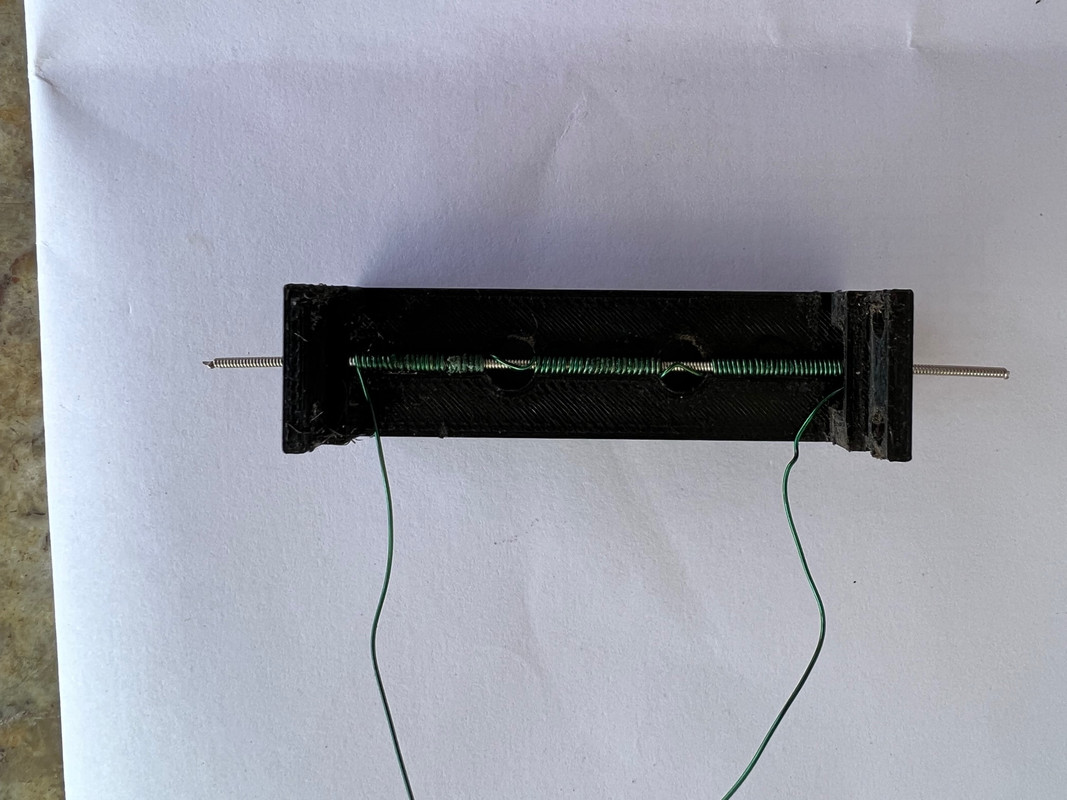 This is mounted over a humbucker located in a holder. 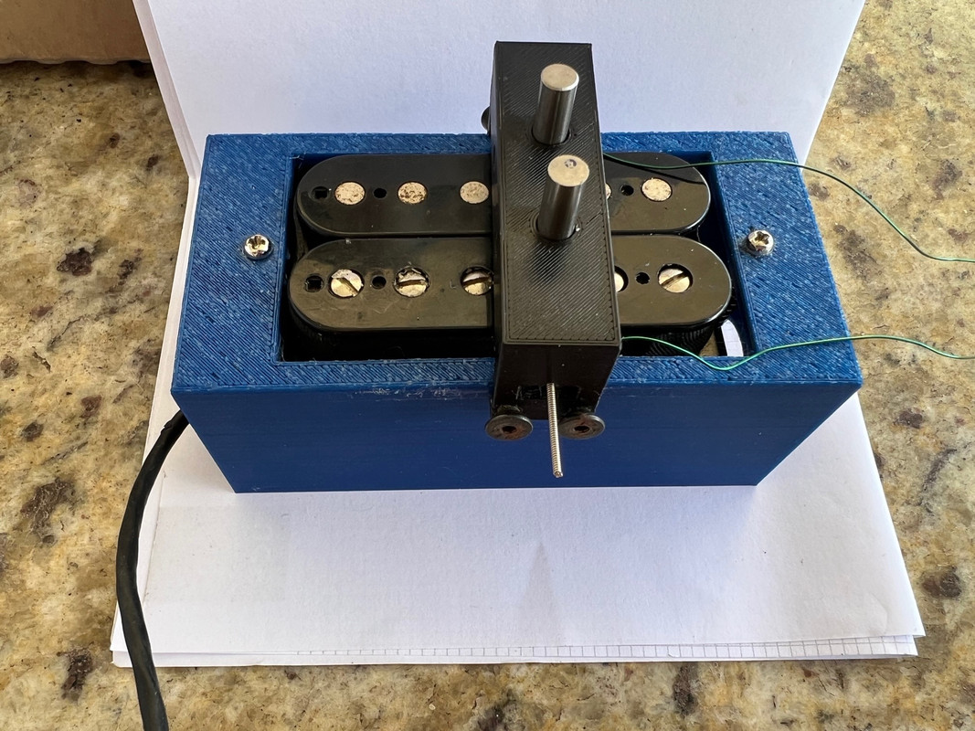 There are a couple of possible problems. First, there are eddy currents induced in the string core. Are they a problem? Second, Does the dc magnetization induced in the string by the pickup reduce the effectiveness of the excitation? For the second problem, the string can be demagnetized by a magnet(s) over the string. This makes some difference for a humbucker, but it is not really necessary since the string does not appear to be fully saturated by the pole pieces. This could be more important for a Fender type single coil pickup. However, even then there is a significant output since the saturation does not occur right over the pole piece since the magnetization goes through zero right over the pickup pole. The current through the exciter coil is from the headphone amp. About 0.1 amp gives a pickup output (SD SH1N) of about 100 mV at 1 KHz. The response of an SD SH1N is shown below. The red line is the response as slightly reduced at high frequencies by eddy currents. The green line is the corrected response. The correction factor is generated from a measurement made with a small low inductance coil, which has very flat response.  Below is this measurement. The exciter coil is down a bit more than 1 db at 10 KHz from eddy currents (assuming that there's not other effects). 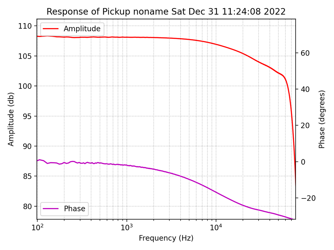 Below is a measurement of a 2.5 H strat type pickup. The higher Q is apparent.  |
|
|
|
Post by ms on Dec 25, 2022 7:03:24 GMT -5
I think the magnetic pull is mostly over the two pieces. The pole piece causes magnetization in the string that is like two thin rod magnets (along the string) with like poles facing each other. The field from the string magnetization pointing toward the pole piece is over it as aquin43 has shown, for example, in the model plot here: guitarnuts2.proboards.com/post/104632/thread. But still that's two points of attraction instead of one, so it would bend the string more broadly, like if you were to tug at the string with two fingers instead of one. Yes, and I like that comparison. Merry Christmas! |
|
|
|
Post by ms on Dec 24, 2022 6:30:38 GMT -5
The two coils also diffuse the magnetic pull over a wider area. The single pole AlNiCo 5 pole pieces pull on the strings in a specific spot, and it induces harmonics when the pickup is underneath the antinode of the harmonic, but since the magnetic field of this pickup isn't as sharply focused, it won't alter the harmonics exactly the same way, but probably still very similar. I think the magnetic pull is mostly over the two pieces. The pole piece causes magnetization in the string that is like two thin rod magnets (along the string) with like poles facing each other. The field from the string magnetization pointing toward the pole piece is over it as aquin43 has shown, for example, in the model plot here: guitarnuts2.proboards.com/post/104632/thread. |
|
|
|
Post by ms on Nov 25, 2022 13:46:06 GMT -5
If the pickup has inductance L and capacitance C, then each coil has inductance L/2 and capacitance 2*C. If you excite one coil, then the other forms a voltage divider with the instrument load. It is a parallel resonance that has a high impedance at roughly twice the pickup resonant frequency. This causes a steep fall off in this frequency range. Details could be more complicated, considering other impedances in the circuit.
As you show, low frequencies are not affected, and so you can get the low frequency gain by measuring the coils separately and adding the voltages. So you can compare the level of an SC and a humbucker.
|
|
|
|
Post by ms on Nov 16, 2022 13:05:22 GMT -5
I agree, but this will give you a comparison between a SC and one coil of an HB, when only one coil is excited (the other one is weakly excited, however). I think you would have to consider the excitation of both coils if it is an output comparison that you are doing, since the string does excite both coils of an HB.
I can't help but wonder, though, what is the purpose of comparing them? Is it, for example, making matched sets of HB/SC for some guitar? It is already common knowledge that HB are louder as far as I know. A really meaningful comparison depends on a reasonably accurate measurement. To make that work would require an exciter test arrangement that can be confirmed by comparison with actual string driven measurements. Also in this case, that would accommodate diverse pickup types. It's possible but not very easy. The problem is not to make it work, but to determine the measurement error confidently.
Measure one coil, and then the other. Add the voltages. To keep interactions down, I like small coils, a short cylinder with a diameter less than that of a pole piece. The coil is placed over a pole, of course. It is useful to measure relative low frequency output levels. Pickups with different frequency responses can be difficult to compare by listening. For example, if you have a resonance above 4 KHz, and lower it in steps by adding C, you might find that it gets louder sounding, presumably because the lower frequency resonance emphasizes harmonics that have higher output. |
|
|
|
Post by ms on Nov 16, 2022 10:44:04 GMT -5
Have you investigated exiting just one coil of a humbucker, or one coil at a time? Remember, the coils are in series, and so they should have very close to the same frequency response, but coupling between the coils could affect the results. How much? You could probably ignore the coupling at 100 Hz and get an output comparison between SC and HB at low frequencies. I think you get a funky result when you put the exciter over just one coil, because rather than get a combined output of the two coils, you get the output of one coil, loaded by the other, which end up being a different response than when both coils are producing voltages simultaneously. Consider the low frequency limit (about 100 Hz, say). The series circuit model consists of a single loop with a voltage source, the two coil resistances, and the load resistance. You measure the voltage across the load resistance. This is a very simple circuit. For example, you can rearrange the other three elements into a different order in the loop, and the measurement does not change. If you excite the coils one at a time and add the results, or excite them both at the same time (not changing the excitation amplitude) then you get the same answer. (That is, if you have two voltage sources in the loop you can add them to make a single voltage source.) |
|


