|
|
Post by JohnH on Nov 12, 2010 7:11:42 GMT -5
At maximum volume, a guitar pickup interacts with the impedances of the pots and other components, the cord capacitance and the amp input to give a characteristic response which includes a resonant peak in the high treble. As you turn down a simple volume control, the shape of the output frequency response changes as the guitar output impedance rises, and the cord capacitance cuts into the treble, which can dull the sound. This is about how to improve the consistency of such volume controls, using treble bleed circuits, and how to build a better treble bleed. I’m showing what happens to the frequency response when you turn down the volume, using four systems: A no treble bleed B a treble bleed capacitor C a treble bleed capacitor in parallel with a resistor D a new and improved design using a variable parallel resistor, based on a dual gang pot for the volume control 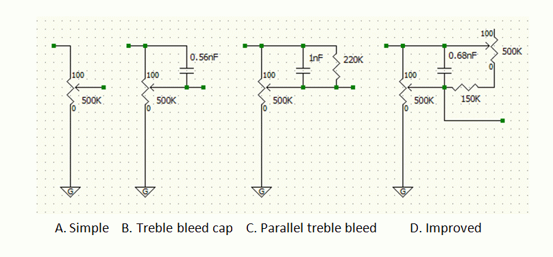 Analysis was done using my GuitarFreak spreadsheet, to model a vintage humbucker, 500k pots, a 10’ cord to an amp. The reference for tone is the tone at maximum volume, and ideally, the shape of the response would not change as volume is decreased. On the following plots of frequency response versus db output, the frequency response is plotted at full volume, -3db, -6db, -12db, -18db and -24db. The three treble bleed designs have each been optimised for -6db to give the closest possible tone to the full volume tone at that level. What is then interesting is to see how consistent they are at other volumes. Full volume and A. no treble bleedFirst, take a look at the top curve, at full volume. There’s a flat response up to around 1kHz, then a peak just over 6db higher at about 3.2kHz, then a sharp fall. 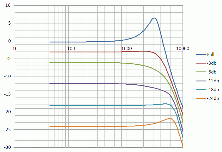 As volume is reduced, the peak is quickly damped down, losing sparkle. This effect is why treble bleed circuits can be useful if this change in tone is judged to be undesirable See also how at very low volume however, treble returns, High gain players who turn right down to clean up the sound may not need these treble bleed circuits. B. Treble bleed capacitor In the second circuit, a single capacitor is used to feed some extra treble to the output to compensate for losses. A 0.56nF has been used, to give a very good tonal match at -6db. 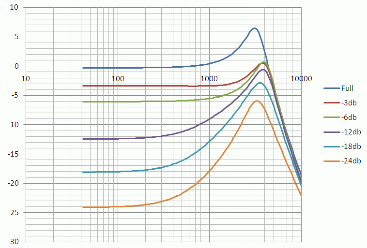 But see how at lower volume, too much treble comes through, the sound gets tinny since bass frequencies are cut more than high frequencies. C. Parallel treble bleed circuitA resistor and cap in parallel give a more consistent result. 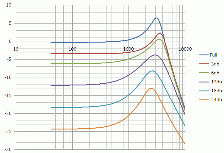 The resistor, combined with the upper branch of the volume pot has a more consistent value in parallel with the cap than the pot alone. So it is better than B. Again the values have been chosen for best results at -6db, but see how the tone at lower volume is still getting excess high frequencies, to a lesser extent than B. Improved parallel treble bleed The optimum values of the TB components are different at each volume level. It would be nice to have a variable capacitor, but this could only be done as a switched arrangement. However it is possible to have a variable resistance. So, the new idea is to use a dual gang 500k volume pot, and use the second half to vary the parallel resistance in a way that makes the tone more consistent. 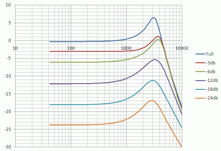 The graphs show that it should work – the response below 1kHz is now much more consistent, and the peak height is also much more even. Anyone want to try it? Cheers John |
|
|
|
Post by thetragichero on Nov 12, 2010 12:19:46 GMT -5
if i remember the next time i put in an order to mouser, i'll order a dual gang pot
all i have are 250k and 500k audio taper pots in my parts box
|
|
|
|
Post by JFrankParnell on Nov 12, 2010 13:41:45 GMT -5
nice  can you please do a wiring diagram for D? |
|
|
|
Post by JohnH on Nov 12, 2010 14:44:01 GMT -5
nice  can you please do a wiring diagram for D? Thanks and I will do that. It will be a drop-in replacement for a normal pot. I wish it was possible to get long-shaft dual gangs? then I'd put them on my LP. The other interesting aspect is to see what it does to the pot taper. The dual gang volume pot for D should be a log pot, and once wired up, it should behave with a taper that is about halfway between log and linear, which I think would be quite good. more later |
|
santellan
Meter Reader 1st Class
  
Posts: 63
Likes: 0
|
Post by santellan on Nov 12, 2010 15:03:00 GMT -5
John,
Just wanted to say what a great job and wealth of information you have provided to this forum.
As for treble bleed circuits do you have any data in regards to the 50's vintage style circuit in comparison with the ones you have listed here?
Thanks
Larry
|
|
|
|
Post by JohnH on Nov 12, 2010 15:42:14 GMT -5
John, Just wanted to say what a great job and wealth of information you have provided to this forum. As for treble bleed circuits do you have any data in regards to the 50's vintage style circuit in comparison with the ones you have listed here? Thanks Larry Thanks larry - I have this thread on 50's wiring: guitarnuts2.proboards.com/index.cgi?board=wiring&action=display&thread=1885I might add some more on that subject however cheers J |
|
|
|
Post by newey on Nov 12, 2010 20:38:58 GMT -5
Good stuff, John! +1 and instantly stickied some we don't lose this.
I'm interested to hear whether the difference between C and D, real world, is significant enough to make one pop for a dual gang pot.
|
|
|
|
Post by JohnH on Nov 12, 2010 21:22:59 GMT -5
Good stuff, John! +1 and instantly stickied some we don't lose this. I'm interested to hear whether the difference between C and D, real world, is significant enough to make one pop for a dual gang pot. Thanks newey - and yes it is not yet proven whether this is useful enough to to be valuable. Most of my guitars either have buffers, or long-shaft pots. But I have my old Shergold, currently with Type C installed. Rehearsing on Thursday I wanted to trim the volume right down but found that the tone was getting thin, which I knew about. I might try the new Type D on this guitar, but when I do I'll be sure to get some sound samples before and after, and also the no-bleed version A too. Meanwhile. heres some more info: 50's wiringSantelan asked about comparison to 50's wiring, so here is the equivalent graph: 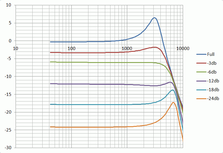 50's wiring puts the tone pot after the volume pot, reducing load on the pickup when the volume is turned down. It does show a useful enhancement compared to modern wiring (ie Type A here), which is why many LP people like it. It does not show the action of the tone control however, which at low volume does not work properly as a tone control (see other thread) Series treble bleed - KinmanThe other basic type of treble bleed not discussed here so far is by Kinman, and comprises a resistor and cap in series (instead of parallel), between the two non-grounded volume pot lugs. Again, it has its devotees, but does not seem to really preserve the shape of the frequency response. The graph is based on a 1nF cap in series with a 120k resistor, which are typical values used for this arrangement. 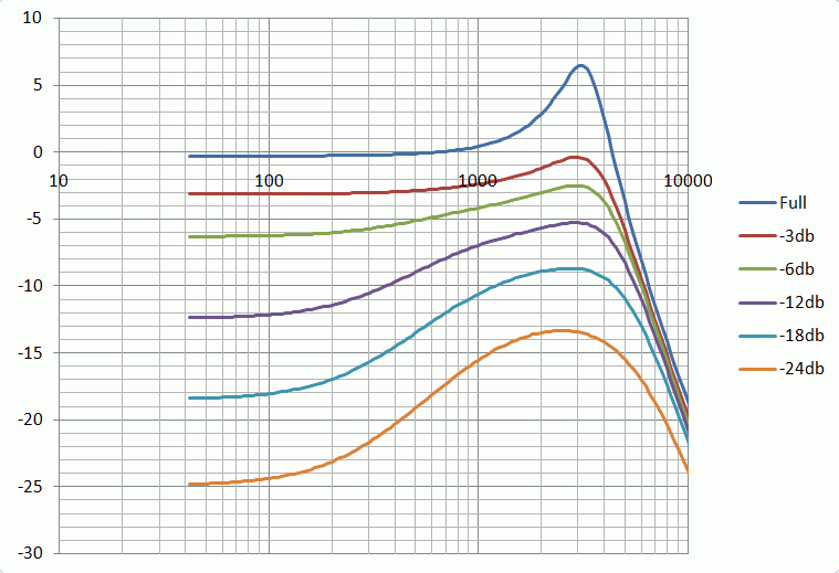 Improved treble bleed - Type D, Wiring diagram Improved treble bleed - Type D, Wiring diagramMeanwhile. here is the wiring for my new arrangement using a dual-gang pot.  cheers John |
|
|
|
Post by JohnH on Nov 12, 2010 22:32:59 GMT -5
The parallel treble bleeds, Types C and D affect the taper of the Volume pot, making the levels fall less quickly. The following graphs are based on the same data, showing output against knob position for a log pot. At the left, the vertical scale is linear in terms of voltage output, while the right graph has a log scale of decibels. Output for a linear pot is shown for reference, and also from a simple log pot (type A and B). The new Type D design seems to have a taper similar to a reduced slope of log pot, and could be quite useful I think. Between 2 and 10 on the volume knob, the result is very close to a true logarithmic response, within 1db, dropping the volume by about 15db gradually over that range. 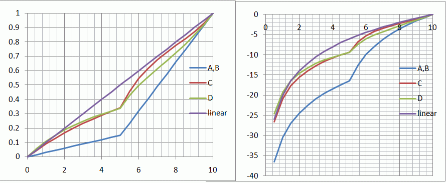 John |
|
Raz59
Meter Reader 1st Class
  
Posts: 71
Likes: 1
|
Post by Raz59 on Nov 14, 2010 19:57:27 GMT -5
John, may I ask your thoughts on the treble bleed that Frank Falbo once proposed on a thread on the jemsite forums? (Please disregard this request if it has already been covered) It's a good idea to try and build a treble bleed in such a way that, at lower volumes, the frequency response is still the same. That dual gang volume pot is probably more ideal than Frank's concept... But, if you don't mind, I'd like to his concept be analyzed in the same way as these circuits. The gist of it is this:   Instead of connecting the TB across input and output lugs of the volume pot, you connect one end of the TB to the volume output lug and the other end to the unused tone lug! The addition of a resistor in series with the capacitor is optional, I guess. I tried this in my strat with master tone/volume controls. In summary, you can have very trebly sounds at low volumes and full tone (equivalent circuit of this situation is System B). But you can reduce the volume of this trebliness by increasing the resistance of the tone pot. The pertinent question is: Can you achieve the ideal 'frequency response' shape with this wiring?Eager to hear the answer! |
|
|
|
Post by JohnH on Nov 15, 2010 6:24:20 GMT -5
Raz – thanks, Ozboomer sent me that circuit also. It seems clever, and might sound OK, but I cant see it matching the sharp peak in the high treble that the full volume sound has. Here’s an analysis from 5Spice of what you posted (but is used a 150k, since that what I’ve seen posted elsewhere). All these have a volume control set to -18db, and the tone pot swepth from min to max. 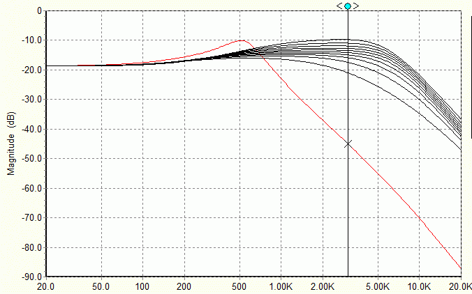 This is what I thought Mr F was describing, just a 330pF TB cap, no resistor, just fed through the tone pot: 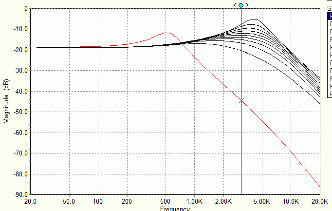 And this is just a 330pF TB cap, and a standard tone pot: 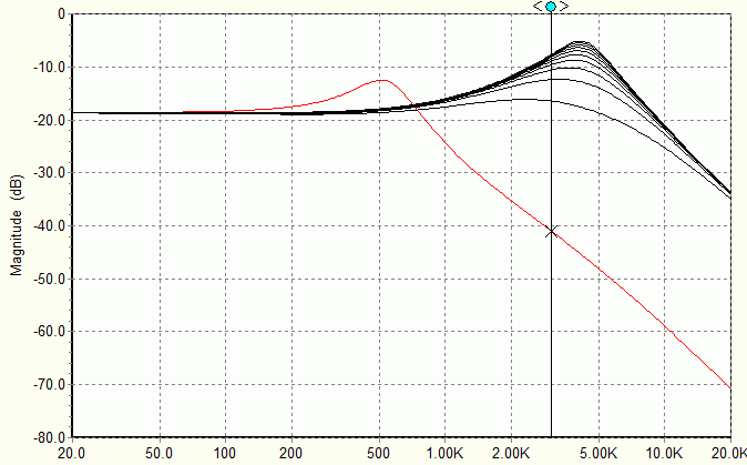 |
|
|
|
Post by JohnH on Nov 19, 2010 18:20:18 GMT -5
Here are some more results from my Treble Bleed investigations. If you are like me, you will find these to be very interesting, and I will therefore feel sorry for you. Results so farFrom what has been discussed above, conclusions so far, from last weeks episode....: - For players who find the dulling of treble at reduced volume to be a problem, passive treble bleed circuits can help
- But TB circuits can only partly compensate, and designs and component values work best over particular ranges of volume and are dependent on the pickups, pots and guitar cord
- We assume the target reference is the tone at full volume, and the ideal outcome is to match that tone as nearly as possible at as wide a range of reduced volumes as possible
- None of the TB designs discussed here affect the full volume tone
- The best configurations are either, a capacitor and resistor in parallel (type C in graphs above), or, the new dual gang idea (type D) presented here, seems to have some merit
Optimising the designsThese were the main circuits being considered:  Back to the story: The next task is to try to really understand the performance of C and D, and optimise the component values of each to get the best possible results, and then to compare them to each other. CriteriaTo make this assessment, some criteria are needed, and this is what I have used: - As before, all tests are based on a PAF-style humbucker, 500k log pots and a 10’ cord of average type
- I will look at the frequency response up to 3.5kHz. This range covers all the significant frequencies, including the peak response. Above this, response will start to fall off, due not only to the guitar but also the amp and speaker (not modelled here). The TB circuits, at reduced volume, do not show as steep a fall of response above this than the full volume tone, and I did not want this to skew any results.
- At a range of volume settings, I’m overlaying the calculated response, with a reference response based on full volume, shifted in overall level to match the reduced volume. Then I’m looking at the maximum and minimum deviation in db through the range up to 3.5kHz, and looking at the difference. For example, if the response curve pokes a maximum 2db above the reference and -0.5db below it, then the range is 2.5db
- For a good result, I’m considering this range should be 3db or less, which could be considered as a match of tone all through the frequency range, with a deviation of no more than +/- 1.5db. the question then is, for each design, within what range of volumes will this criterion be met?
Here’s an example: 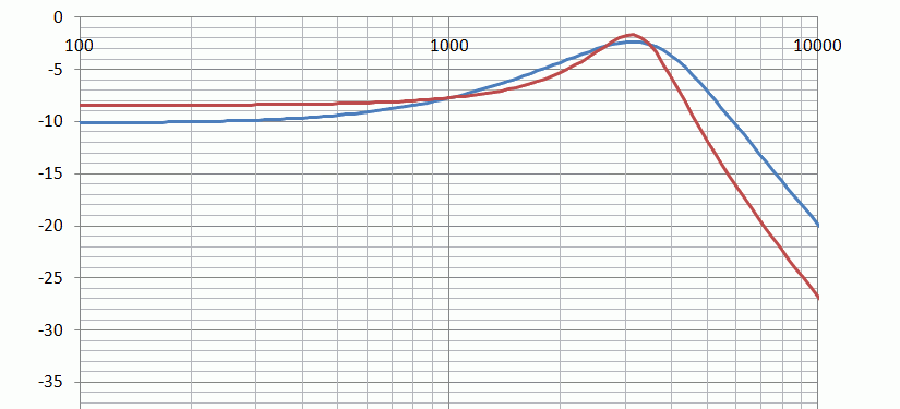 In this case, it is a standard Type C TB circuit with a 1nF cap and 220k resistor, and a volume knob setting of 5, for about a -10db volume reduction. The red curve is the reference, and the blue curve is a maximum of 1.7db below it and 1.0db above, within the range up to 3.5kHz. So the overall range of deviation is 2.7db, and I’m calling that a good result, being less than 3db. Anyone follow that? Design candidates- From previous results, the best capacitor values tend to be around 1nF or a bit less, so I’m testing 0.82nF and 1nF
- For the Type C design, 220k has been my usual value, but at lower volume, a lower resistor seems to be better, so 220k and 150k are tested here
- For the new Type D design, the fixed resistor in series with the 2nd part of the pot seems better at 120k than at 150k, so 120k will be used.
So there are 6 designs to test ResultsHere are the graphs of db deviation range vertically, against knob position horizontally, for the two dual-gang and four simple parallel designs. 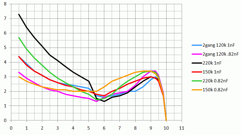 The first thing to see is how the black line, representing the 220k and 1nF that I usually suggest, works very well down to about 5 on the control, and then deviates more below that. This corresponds well to my own impression of this combination, in which the sounds gets noticeably thin below half way. At the upper end, all results show no deviation at 10, as expected, then get to a maximum error at around 9 to 9.5. This represents a drop off in the treble peak response, which then returns at lower volume. The control in this region is all down to the cap value, and 1nF does better than 0.82nF in all designs At around 5, all the circuits are showing good control of tone Below 5, a smaller cap works better than a larger cap, and so the ones with 0.82nF are better. The new design D, works well, but what is very interesting is that the simple (type C) designs based on 150k resistance work almost as well, and better than with 220k. If you look at the red (150k 1nF) and blue lines (dual gang with 1nF), they both manage to stay within 3db deviation at high volume, and both stay within this range all the way down to about 2 on the knob. The blue line, representing the dual-gang system with 1nF, is about 0.7db better around 8 but there’s not much to chose between them really. ConclusionsTentative conclusions, subject to actual testing on a guitar: - For a simple parallel treble bleed circuit, 220k and 1nF works well down to 5 on the volume control, but overall, it could probably be improved by substituting a 150k for the 220k, resulting in better tone at low volume
- If control at low volume is more important than high volume, then a 0.82nF cap may be better
- The Dual-gang design is worth a try, it provides slightly better consistency and has a more even pot taper, but its not ‘likely to be dramatically different
Comments on other pickups and cord lengthsAll the above is specific to the pup, pot and cord values tested. However, I have done a bit of investigation with other cord lengths, pot values etc. I did find that with a cord with greater capacitance, like a standard 20’ cord, it is very difficult to keep any consistent control on tone with volume. No doubt this is of negligible concern to most players, but for those who care, I think 10’ cords are the best. This can be from guitar to stomp-box / buffer, then any length after that is fine. If a 20’cord is needed for practical reasons, the types with low capacitance (some are just 15pF/ft) could be used, to match the values used in these assessments. For absolute consistency at all volumes, and buffer at the guitar or a wireless system provides a solution Single coils, and different pot values are likely to have a different set of optimum values for treble bleed, if this is judged to be necessary at all. cheers John |
|
chase
Apprentice Shielder
 
Posts: 30
Likes: 0
|
Post by chase on Nov 20, 2010 22:07:13 GMT -5
Brilliant thread, John. It's so nice to see a scientific approach instead of the usual subjective voodoo so prevalent elsewhere. I have a custom guitar in the works which will be using the pickup selection circuitry we discussed in another thread, so while it's still a ways off I'll definitely be consulting this thread again.
|
|
|
|
Post by JohnH on Nov 20, 2010 22:24:03 GMT -5
Thanks chase
Based on what the numbers were saying, this morning I changed the treble-bleed ciicuits in my LP from 220k 1nF to 150k 1nF. It seems really good, and I would never have guessed it. It has good powerful tones all the way down almost to zero volume.
At high gain, I can get a deep hard-rock crunch even at a guitar volume knob setting of 1!
Turning down, it actually sounds slightly clearer than at full volume, but with no noticeable bass loss. the pot taper has become more controlable and easier to set mixes of neck and bridge. It seems to work in all modes, including series and coil-cut too.
So this will now be my base recipe for these circuits.
cheers
John
|
|
|
|
Post by irwired on Nov 22, 2010 11:45:06 GMT -5
Thanks John A fine job of sorting the variables!!!!!!!!! and a very clear explanation even i can understand  It's time to open em up and fire up the soldering irons. or as we do here in Phoenix.......just lay them out in the sun for a minute  Cheers IRW |
|
|
|
Post by newey on Nov 22, 2010 14:40:31 GMT -5
. . .right next to that egg you're frying on the sidewalk, right?
|
|
|
|
Post by irwired on Nov 23, 2010 9:54:11 GMT -5
They fry up fine if you don't mind a little grit.  |
|
|
|
Post by 4real on Nov 23, 2010 23:18:13 GMT -5
Just a quick word of encouragement...great work as always john...
On Dual gang pots...as it happened, the push pull pots i have been using in recent projects like the LP and Tele and if people recall my "uber-switch-pots" for the strat project I really must revisit...are dual gang audio taper pots. I don't recall which asian eBay supplier they came from and they are not the absolutely highest quality, but they do work! The dual wiper thing seems to be a part of the design.
Another tip is that you can take these things apart and get a similar pot and fit the two together to mix and match...so you get the switch mechanism and pot with a different resistance value. For my sustainer circuits for instance they require a 1K pot and I use the push pull for the harmonic function. This might be useful for people with both singles and HB's in a guitar so they could simultaneously have 500K and 250K ranges on the same control...just a thought...plus the P-P function.
Regardless, these things can take up very little more space than a single pot for no extra cost and even have the switch capacity.
I know in general your LP's require long shaft pots, but it is possible with care to use a spade bit or forestner bit to carefully thin the top to something usable with standard pots and switches...obviously extreme care is needed. Some LP copies like my chinese version already came with a cavity deep enough to just allow the use of standard pots like these.
anyway...my 2c...must work out where I got them from as I am down to my last few and probably need some more...I bought a pack of 10~!
|
|
|
|
Post by JohnH on Nov 24, 2010 14:46:42 GMT -5
Thanks Pete. and those dual-gang push pulls sound like useful things to have in your spares box, particularly if they are openable without trashing the switch.
On the treble bleed study - the next thing I intend to post will be about using longer cables such as 20'. From the numbers Im getting, it seems that below about 7 volume, a 20' cable sounds very similar to a 10' (a bit less high presence), with big changes occuring from 7 to 10 resulting in a lower frequency for the peak. So Im thinking that my advice on TB components will probably not be different (conveniantly). Although there is less consistency of tone, it will hopefully still sweep through a range of usable tones. This needs testing on a guitar, and I'll be putting up some sound clips.
John
|
|
|
|
Post by JohnH on Nov 26, 2010 19:09:31 GMT -5
Here’s the final instalment for now, to do with using different lengths of lead. A 20’ lead has twice as much capacitance as a 10’, so at max volume, the resonant peak is at a lower frequency. But what happens at lower volume? This graph is with the 150k 1nF treble bleed components, which I believe are a good combination in both cases: 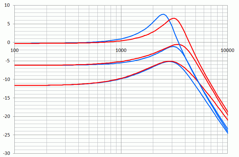 [red] Red is with a 10’ cord [/red]and [blue] blue is with a 20’ cord[/blue], and traces are provided at full volume, -6db (5.5 on the knob) and about -12db (3 on the knob). It is interesting that the two cord lengths have quite similar results at lower volume. Sound SamplesAnd now some sound samples. These are from the bridge pickup of my LP, now with 150k and 1nF treble bleed, through a cord, to a neutral buffer and then to the pc. The sounds are all normalised for volume (ie the reduced volume samples are boosted back up to the same volume level in the computer), and what you hear is a bit of Foo Fighters chord strumming played four times as follows: Full volume with 10’ cord Volume at 3 with 10’ cord Full volume with 20’ cord Volume at 3 with 20’ cord www.soundclick.com/bands/page_songInfo.cfm?bandID=674084&songID=9921828The tones all seem OK to me, but there is a noticeable extra high treble in the reduced volume samples, and you can hear how the 20’ full volume has less edge than the 10’at full volume, but is quite similar to the 10’at low volume. These frequencies are of a value where a normal guitar amp will start to reduce them. So here’s the same group of samples, this time EQ’ed with frequencies ramping down by about 20db from 4kHz to 5khz, and upward, to roughly mimic a clean amp: www.soundclick.com/bands/page_songInfo.cfm?bandID=674084&songID=9921829ConclusionSo there it is. Overall conclusion for humbuckers with 500k pots: A parallel treble bleed circuit of 150k and 1nF works pretty well! cheers John |
|
|
|
Post by JFrankParnell on Nov 26, 2010 19:24:43 GMT -5
the 10' has more sparkle, less muffle than the 20', right? I thought the buffer was sposed to eliminate that?
but, I agree, the tb works pretty well!
|
|
|
|
Post by newey on Nov 26, 2010 19:29:32 GMT -5
It does, after the buffer. Two different cable capacitances pre-buffer will still affect the frequency curves, as shown.
|
|
|
|
Post by JFrankParnell on Nov 26, 2010 20:24:22 GMT -5
ah, ok. hence, the onboard or in-cord buffer...
|
|
|
|
Post by irwired on Nov 26, 2010 21:20:05 GMT -5
Just Great......................................... ;D ;D ;D ;D ;D ;D i added the 1.5k resistor in parallel with th 1nf cap to my Reverend today and the sound at low volume is "clear and bright" (to borrow a phrase from the Kinks) and the base is balanced and has good sustain.  I apologize for not posting sound samples but i have only recently become nutty and haven't figure that part out yet.   I cannot adequately express how good this sounds and how grateful i am for the guidance and expertise of John H. Thank You IRW I will revise my thread on the Reverend and complete the wiring diagram. I have some pictures as well to post. Cheers  |
|
|
|
Post by ashcatlt on Nov 26, 2010 21:30:50 GMT -5
John, while I haven't been able to listen yet (iPhone speaker won't do us any darn good) I have noticed in your graphs that the center of the resonant peak seems to wander around. I wonder if that's what you were hearing in the straight buffered version?
You've talked so far about how this affects the y axis, without really talking about the x.
|
|
|
|
Post by JohnH on Nov 26, 2010 22:15:55 GMT -5
Ash – yes partly. And the difference in the peak frequency at full volume on a 20’ cord is very noticeable. When checking out different arrangements, I found it easier to control the peak magnitude first, then the linearity at lower (<1kHz) frequencies second, which is what guards against apparent lack of bass. The peak frequency itself does what it does.
I set my criterion to test the match of tone at every frequency up to 3.5kHz, so if large changes in the peak response fall in that range, then they got picked up and effectively included in the results.
Irwired - glad that worked for you, and hoping its with a 150k resistor instead of 1.5k, otherwise I might need some different maths!
|
|
zirltzn
Meter Reader 1st Class
  
Posts: 68
Likes: 0
|
Post by zirltzn on Apr 3, 2011 11:52:55 GMT -5
great explanation. i can vouch for the "150k 1nF" over the "220k 1nF". tried both on my strat with John's 16+ tones schematic. i thought the 220k would have been better, but in actual practice, 150k does work better.
|
|
|
|
Post by JohnH on Apr 4, 2011 5:51:25 GMT -5
great explanation. i can vouch for the "150k 1nF" over the "220k 1nF". tried both on my strat with John's 16+ tones schematic. i thought the 220k would have been better, but in actual practice, 150k does work better. Thanks for posting that. It's useful to hear about that comparison with different pickup types, to support the theoretical results. |
|
|
|
Post by ashcatlt on Apr 7, 2011 11:45:17 GMT -5
There is currently a thread on the DIYstompboxes forum discussing this thread. So far mostly opinion, but that's a large part of what this is about anyway. One dude mentioned using a separate pot in place of the fixed resistor so you can dial in the response that you want or need for specific situations. |
|
|
|
Post by genmce on Oct 16, 2011 11:18:11 GMT -5
So how would the values (resistor/cap) change when using a 250k audio volume pot for type B or type C above, on my mim strat?
I get treble drop off quickly on the volume pot.
Thanks.
|
|


 can you please do a wiring diagram for D?


