bpf8hz
Apprentice Shielder
 
Posts: 35
Likes: 0
|
Post by bpf8hz on Oct 11, 2023 4:59:19 GMT -5
hello world
I've got a 3-pickup SHS axe with regular 3-position switching for neck & bridge and a mini ON-ON-ON switch controlling the middle pickup (only mid/mid + 3 pos/only 3 pos). For the sake of simplicity it can be assumed that we are talking about a regular 2-pickup SS switching system (as the middle pickup switch exists on its own), effectively something like a Tele.
Recently I thought it'd be nice to convert the standard 3-way neck & bridge switch to a 5-way superswitch, and so the Schaller Megaswitch M was chosen to serve the purpose.
I came up with a list of configurations I'd like to see (or hear, actually): - Bridge
- Bridge + neck in series, out of phase (probably with a cap)
- Bridge + beck in parallel, in phase
- Bridge + neck in series, in phase (probably with some sort of a shunting resistor at the output to permanently "roll back the volume" at this position so it is not so muddy) - open for suggestions for this position
- Neck
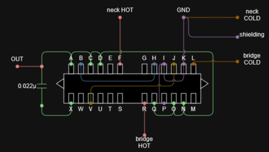
Actually it seems like a rather common arrangement for the 24-pin switching horror show that a superswitch/megaswitch is. So I got my Megaswitch M and took a good hard look at Schaller's website documenting their SS3 wiring ( link, scroll to bottom): This isn't what I want exactly, but I thought I'd figure it out once Schaller's wiring is up and running. That, however, was not to happen: all the positions were messed up. Some were thin (not OOP-thin, more like an incorrectly connected pickup), some were extra muddy as if the tone was almost rolled off, some were duplicating the others, some had a pickup pass the screwdriver test when it shouldn't. TL;DR: it was a broken mess, sometimes similar to what has been described here.
I have since tried to adapt some Superswitch wirings I've found online (including this fine place) using the Superswitch-Megaswitch contact translation table from here/ here to no avail. Every time switching was completely out of place, even with a carefully replicated wiring from here (search for "Megaswitch", it's the only one on that page). However, I have succeeded in wiring a cheap low-quality Superswitch clone using a wiring I found at this TDPRI page, so the problem seems to be isolated to my particular Megaswitch M.
After trying out different wirings for the Megaswitch and failing miserably, I'm thinking it's likely I've got a faulty switch on my hands. Still, I would like to make sure I got the actual wiring diagrams correctly. I've made a few myself - I'll try to attach them in a follow-up post, as image uploads in the thread creation form don't seem to work for me. The diagrams are: - complete wiring of my guitar that I've yet to implement (I copied some Superswitch wiring there, can't remember which one exactly but it was similar to what I wanted to achieve)
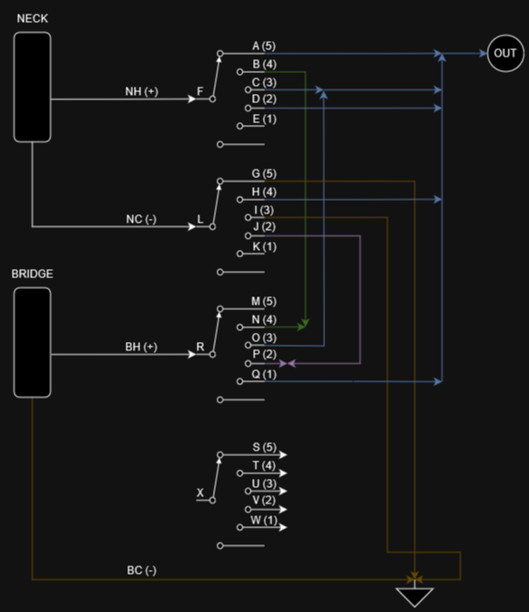
- redrawn Schaller SS3 Megaswitch M wiring
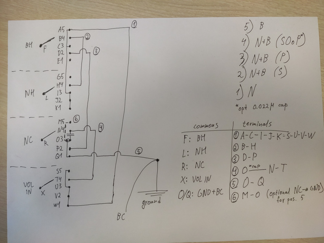
- an attempt at creating a Megaswitch M wiring diagram for my needs from scratch
Those are drafts at best. Regarding the "yet to implement" thing - right now my guitar has a neck & bridge pickup switch, middle pickup switch, vol+tone wired the 50's way and a killswitch.
Anyway.
I might be slowly slipping away from the actual topic, so back to it. Has anyone encountered Megaswitches broken from the factory? Does anyone have a Megaswitch M wiring for the positions I'm looking to achieve? Maybe someone could comment on the correctness/complete incorrectness of the diagrams I linked (especially the hand-made ones)? Any word of advice is much appreciated.
I've ordered another Megaswitch M as I'd need one for another guitar anyway, so I hope to test the "faulty hardware" part myself.
I'd also like to note that "just getting a regular Superswitch" isn't an option as the quality (nice-feeling) ones are quite expensive here + I'd really like to use a far more compact and nice-looking Megaswitch. As a bonus it'd be nice to have a guitar of German descent with a matching tricky switch 
Hope I've managed to stay on topic and not fill this wall of text with practically insignificant details.
|
|
bpf8hz
Apprentice Shielder
 
Posts: 35
Likes: 0
|
Post by bpf8hz on Oct 11, 2023 5:11:37 GMT -5
Homebrew wiring diagrams: |
|
|
|
Post by newey on Oct 11, 2023 5:19:36 GMT -5
bpf8hz-
Hello and Welcome to G-Nutz2!As I was reading this tale of woe, "bad switch" popped into my head. Off to work at the moment so no chance to check your diagrams at present, but someone will be along. Did you check the switch operation with a multimeter?
|
|
bpf8hz
Apprentice Shielder
 
Posts: 35
Likes: 0
|
Post by bpf8hz on Oct 11, 2023 5:27:29 GMT -5
I've checked it at least in some way - obviously I was too lazy to probe all the combinations of those 24 lugs (that would be A LOT), but all the switching groups (according to Schaller schematics) looked fine... At least that's what I seem remember.
|
|
|
|
Post by newey on Oct 11, 2023 11:45:22 GMT -5
Some were thin (not OOP-thin, more like an incorrectly connected pickup), some were extra muddy as if the tone was almost rolled off, some were duplicating the others, some had a pickup pass the screwdriver test when it shouldn't. TL;DR: An internal problem with the switch could result in those types of issues if two lugs are connected but have significant resistance between them. But it sounds like more than just that if things were connected where they shouldn't be. Well, you probably could spot a problem without going through all possible combinations. If you find one bad one, that's reason enough to ditch the switch. |
|
bpf8hz
Apprentice Shielder
 
Posts: 35
Likes: 0
|
Post by bpf8hz on Oct 12, 2023 3:35:09 GMT -5
Well, you probably could spot a problem without going through all possible combinations. If you find one bad one, that's reason enough to ditch the switch. Sure thing. I have actually found some combos where my meter shows R of a few hundreds kOhms and even some negative values if I switch the upper R limit to 2000K on the meter (that might be some kind of a measuring error in the meter, IDK). I did that on an already wired-up switch, however; I'll clean one up from all the jumper wires and try again. I got that other Megaswitch yesterday and tried wiring it up the Schaller SS3 way according to the re-drawn homebrew diag (see pic 2 here). To my surprise, I experienced the same symptoms. I disconnected the neck pickup wires and tried fiddling with the bridge wiring a bit; strangely enough, I found that with the hot wire connected to the switch, touching the cold wire had the same effect as touching the jack tip - antenna mode mode engaged in all positions. That last bit is concerning - I'd understand if it happened only in bridge(+something) positions, but all five were affected. With that in mind, I think this thread might actually be a candidate for a "wiring request" category, it seems  I highly doubt that I got myself two faulty switches in a row, and all the electronic guts other than the Megaswitch seem to be OK - once again, I have successfully wired a Superswitch clone for a test. TL;DR - it's looking more and more like a Megaswitch wiring issue. [Wiring request], anyone?  |
|
bpf8hz
Apprentice Shielder
 
Posts: 35
Likes: 0
|
Post by bpf8hz on Oct 12, 2023 3:39:47 GMT -5
I think I'll also try to wire that Megaswitch as a regular 5-way to test the switching function with a wiring that's simpler and easier to understand. If no new ideas surface before I find the time for it, that is.
|
|
|
|
Post by newey on Oct 12, 2023 5:21:11 GMT -5
Just spitballing here, but it also occurred to me that there are several different types of Megaswitches. Not all of them have the same lug arrangements, but some do have the same number of lugs. Are you sure yours is the "M" model?
Although just as it would be odd to have 2 bad ones shipped to you, it would similarly be odd if they shipped you the wrong model twice. I don't have the time at the moment to check the diagrams but that's probably the next step. Glad you did get it working with the superswitch at least.
|
|
bpf8hz
Apprentice Shielder
 
Posts: 35
Likes: 0
|
Post by bpf8hz on Oct 12, 2023 5:27:43 GMT -5
Just spitballing here, but it also occurred to me that there are several different types of Megaswitches. Not all of them have the same lug arrangements, but some do have the same number of lugs. Are you sure yours is the "M" model? Yes, the ones I've got have the M branding and A to X contacts; IIRC only the M model has that many. Effectively it is (or at least it ought to be) a re-arranged and more compact version of a regular superswitch as shown here and here. AFAIK other Megaswitches (P, E, etc) are internally pre-wired to some degree, thus allowing for only a subset of superswitch wirings.
I wonder if Schaller could make newer switch revisions (or something like that) and forget to update their docs. I couldn't find any info on the matter, though.
|
|
bpf8hz
Apprentice Shielder
 
Posts: 35
Likes: 0
|
Post by bpf8hz on Oct 27, 2023 6:43:39 GMT -5
Just got a spare minute to re-draw the wiring diagram once again. Terminal numbering/lettering according to Schaller's Megaswitch M diagrams. Could someone review this one? Seems legit to me, but who knows. BC, BH, NC, NH are bridge/neck cold/hot, respectively. P.S. Didn't have time to test the switches yet and my meter's probes got FUBAR'd, so that will have to wait a bit. |
|
|
|
Post by newey on Oct 29, 2023 6:56:51 GMT -5
Your diagram reads OK to me, except I'm not sure on the "optional" cap, that may just be a problem of me reading your diagram, but the cap's connection at position 4 is unclear.
There is no need to ground the NC at position 5, the NH is disconnected anyway, so just leave both ends disconnected.
Also (and this is just our convention here, not a universal method) we tend to use an "X" for a series connection and a "+" for parallel. So, we would usually call your position #2 "N X B OOP" instead of "N + B (series OOP)". But that's just nomenclature.
|
|
bpf8hz
Apprentice Shielder
 
Posts: 35
Likes: 0
|
Post by bpf8hz on Oct 30, 2023 1:42:16 GMT -5
Your diagram reads OK to me, except I'm not sure on the "optional" cap, that may just be a problem of me reading your diagram, but the cap's connection at position 4 is unclear. That may as well be my misinterpretation of how the so-called HOoP is done. As far as I understand, the cap essentially bleeds some bass that's lost as a result of phase cancellation. I really don't like the term "half out-of-phase"; from my point of view the signal is OoP'd 100%, then the bass bleed occurs. I might be completely wrong, though  Here's a little diagram for positions 2 and 4: That optional cap connects terminals O and N in the switching diagram; those terminals are NOT to be shorted should the cap be removed. I thought it'd be better (not in a practical way - something like a "best practices" thing, I guess) to have the cold wire grounded all the time as it is done with regular switching schemes. Here, however, NC is essentially switched to being "hot" at least once (pos. 4), so it really seems entirely pointless to ground in in pos. 5, yeah. Thanks for pointing that out, mental note taken  I've stumbled upon X's and +'s here and there, but wasn't completely sure what that would mean in a given context. |
|
|
|
Post by stevewf on Oct 30, 2023 10:26:29 GMT -5
Here's a little diagram for positions 2 and 4: If I can jump in here: I think that cap should be in a different spot for "OoP", and that in the above drawing, that cap will simply act as a Tone cap, since it shorts the overall Hot with the overall Ground when in position 4. Instead, that cap should be in either one of these two positions: Shorting BC & BH or shorting NC & NH. In the big schematic, that'd put the cap between terminals either: -between terminals B & O (or Q or Ground) - this would "half" the bridge output -between terminals H & N - "halfing" the neck output ...if I'm getting it right! |
|
bpf8hz
Apprentice Shielder
 
Posts: 35
Likes: 0
|
Post by bpf8hz on Oct 30, 2023 23:48:55 GMT -5
If I can jump in here: I think that cap should be in a different spot for "OoP", and that in the above drawing, that cap will simply act as a Tone cap, since it shorts the overall Hot with the overall Ground when in position 4. Instead, that cap should be in either one of these two positions: Shorting BC & BH or shorting NC & NH. In the big schematic, that'd put the cap between terminals either: -between terminals B & O (or Q or Ground) - this would "half" the bridge output -between terminals H & N - "halfing" the neck output ...if I'm getting it right! Indeed, I completely missed that somehow. Been listening far too much Blur lately, now my eyesight is behaving accordingly  Thanks for pointing it out! Anyway, think I'll have to email Schaller and see if they could help. It seems I've hit the dead end; tried wiring it all up yesterday only to get similar symptoms yet again. I highly doudbt the switches are faulty per se, now that I have two of them behaving the same way. They both have the E327080 imprint. Maybe someone with a *working* Megaswitch M could chime in and look around the switch chassis/PCB for a similar imprint? |
|
|
|
Post by newey on Oct 31, 2023 11:57:03 GMT -5
P.S. Didn't have time to test the switches yet and my meter's probes got FUBAR'd, so that will have to wait a bit. Given all the head-scratching we're doing on this problem, that should be your first step before you contact Schaller. Make sure the switch is doing what they claim it's supposed to be doing. Also, when you say that the switch isn't working, when you had it wired, were you getting any sound at all? In some setting of the switch but not others? IOW, I don't think we've yet had a sepcific description of what, exactly, the failure is here. |
|


 Thanks for pointing it out!