|
|
Post by newey on Apr 25, 2024 16:03:54 GMT -5
|
|
|
|
Post by newey on Apr 25, 2024 16:01:46 GMT -5
Yes, the path straight from the CCW lug to the wiper will be the "path of least resistance" as opposed to the path that goes through the cap to ground.
|
|
|
|
Post by newey on Apr 25, 2024 15:53:56 GMT -5
The cap is not "overshadowed" by the pot's resistance, the cap is effectively out of the circuit at "10" on the pot. At that point of rotation, the CCW lug is effectively connected straight to the wiper, bypassing the pot's resistive element. The cap operates through the resistance of the pot (and then to ground a frequency-dependent portion of the signal) and so has no effect when the pot's resistive element is out of play.
Here's an eperiment that I found helped my understanding of pots. Measure with a multimeter between the 2 outer lugs of a pot. This will give you the total resistance value. A 500K pot won't be exactly 500K but it sould be within about 20% of the stated resistance, as most guitar components are made to a 20% tolerance, plus or minus. Then, put the meter between the CCW lug and the wiper, with the knob/shaft at 10, Slowly turn the shaft and measure the resistance at, roughly, 9, 8, 7, 6 etc, all the way down. Watch how the resistance changes as you turn the knob down. This is of course nonlinear with a log taper pot (or antilog taper)
|
|
|
|
Post by newey on Apr 25, 2024 15:47:09 GMT -5
Could the existing (now presumed non-conducting) conductive paint mess with a new coating of conductive paint, if it turns out that parts of the existing paint is still conductive? Either something conducts well (only a few Ohms resistance at most) or it does not. Adding more conductive paint shouldn't increase the resistance. |
|
|
|
Post by newey on Apr 25, 2024 15:32:21 GMT -5
So the cap really has no effect when a tone pot is at 10? Effectively, yes, unless your pot is faulty. You can test the pot with a multimeter if it is out of the circuit. With the pot shaft rotated full clockwise (unless you're wiring for a lefty), between the wiper (center lug) and the CCW lug you should see only a negligible resistance. I start to sound like a scratched LP on this topic as I've said this so many times. Test all components, even brand new ones, before installing in a guitar- pickups, switches, pots- everything. It only takes a couple of minutes to check it all but that couple of minutes can save hours of troubleshooting if you wire a bad piece into the guitar and have to sort it afterward. (not implying you don't already do so, stateofepicicity, but for the benefit of all who may read this in the future) How do I know to do this? I learned the hard way with a broken pickup that I couldn't figure out why it wasn't working in the guitar. Our late mentor ChrisK advised me after that to not only check each component, but to take notes on every build- pickup DC resistances, pot values, wiring diagram used, etc. I now do so regularly, it not only helps with troubleshooting problems, but also if you go back in to the wiring years later and can't recall exactly what you did years before. |
|
|
|
Post by newey on Apr 25, 2024 11:30:26 GMT -5
OK, let me take another look at this. I didn't work from the prior diqagram as so many changes were involved.
|
|
|
|
Post by newey on Apr 24, 2024 19:47:56 GMT -5
revo- Hello and Welcome to G-Nutz2!Without putting pen to paper (primitive tech, to be sure, but that's just me) I can't say for sure - but I think what you propose is possible with the components you are describing. Actual work intrudes at the moment, so it would probably be awhile before I could work out a diagram. (SO, if someone wants to jump in . . .  ).
|
|
|
|
Post by newey on Apr 22, 2024 20:57:40 GMT -5
cem- Sorry for the delay on this. I think this should be OK and hopefully I've kept the right coils for the coil cuts. But let's get another take on this before you wire it, stupid errors are common with my diagrams!  Note that, to show the pots clearly, I have rearranged them from their physical locations in the guitar. You can, of course, put them through whichever of the 4 holes you wish provided you make the wires long enough. 
|
|
|
|
Post by newey on Apr 19, 2024 11:08:00 GMT -5
cem- Sorry no one got back to you sooner on this. I don't see a problem with what you propose. Give me a few days to take a look and see if I can get a diagram together for you.
|
|
|
|
Post by newey on Apr 10, 2024 20:22:43 GMT -5
until newey posts us a picture! Worth a whole bunch of words, as they say . . . 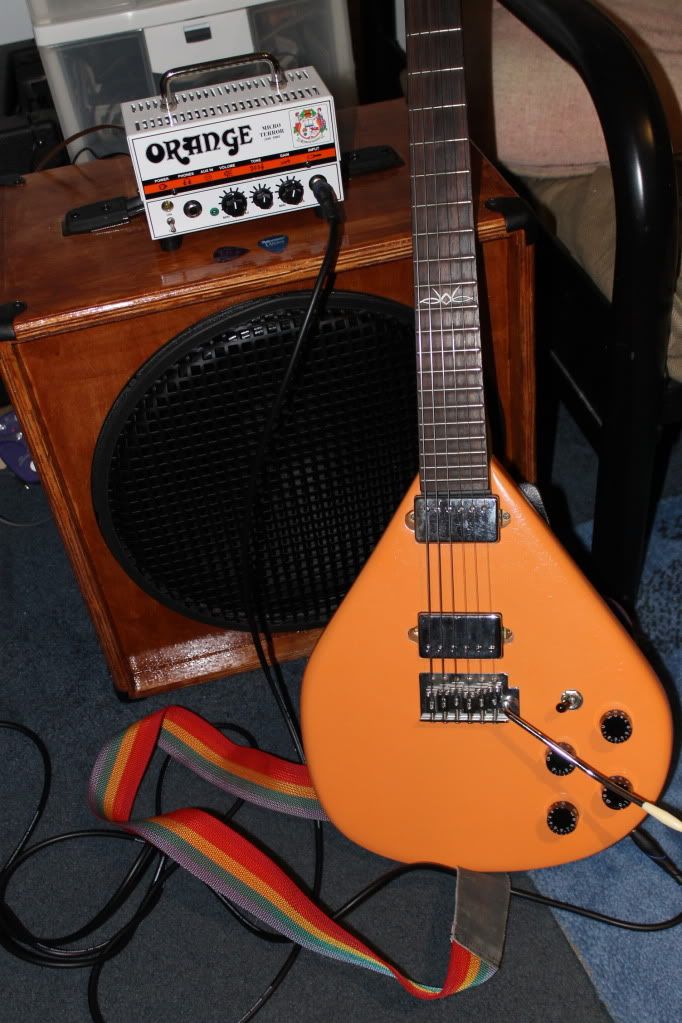 When I originally did this back in about 2009 or so, I had it wired with the "Peter Green Mod", where in the center position on the 3-way switch, the pickups are out of phase. It was interesting for a while, but several years ago I rewired it back to a standard 2-HB wiring. |
|
|
|
Post by newey on Apr 10, 2024 11:21:41 GMT -5
I'm hoping after the downsizing, you still have the electric pumpkin? The infamous pumpkin isn't going anywhere! mikecgThe Tascams I bought with the headphone amp (not sure of the model) were about the same money, about $30 USD. Can't really compare them to better headphones as I wasn't familiar with the sound of the amp, would have to use the stereo with a well-known piece of music like Dark Side or something to really compare. I have an old pair of Sennheisers that I have used with the stereo for years that I could compare these to, the Sennheisers certainly cost me a lot more money "back in the day" as they say. But these seem just fine. I wanted to get a pair of closed phones for the headphone amp and these were the cheap option. |
|
|
|
Post by newey on Apr 9, 2024 20:19:37 GMT -5
So, several months ago Mrs. Newey and I sold the house and downsized to an apartment, which we are loving. As empty nesters, we were payimng to heat/cool/maintain a whole lot of square footage that we weren't using. But as part of the downsizing process, the guitar stable was cut back pretty substantially, and several amps went as well. (The trusty old Peavey I stashed at the cabin, where I visit it and give it the love it deserves about monthly.) And, I still have the Quilter pedal amp and 10" cab in the apartment, but I can't crank it much- We now have upstairs neighbors, one of the downsides of apartment living. A new rig was needed. So, I hit up Musician's Friend for a headphone amp and a pair of headphones. I bought a Vox Amplug "AC30" and a pair of Tascam cans. Unbeknownst to me, I had a bunch of reward points from purchases I made years ago at MF, so I only paid about half of the ticket price. Anyway, got this today, my new apartment-friendly rig:  Does it sound remotely like an AC30? Mind you, I haven't played through a Vox AC in probably 35 years, but, no, I don't think it sounds like an AC30. And I still have a learning curve with this thing, the documentation that comes with it is horrible, it basically tells you to go online and download an owner's manual. Which I will do, but in the meantime, I'm toggling through effects settings without knowing what they are or how, exactly, to change them. And, being tiny, the controls are tiny and take a light touch. But my first impression is that it is pretty good at what it does. Some of the effects were underwhelming. The tremolo is good, though, that part sounded quite "Vox-ey". And the chorus effect sounded pretty good, too. I don't know if there's a true reverb in there or not, maybe I just haven't found it yet (as the instructions have zero information!). There is what sounds like a pretty boomy coliseum echo effect that I played with for a while. I wasn't able to find a gain setting that sounded very good, but again, there is more to explore yet. The clean setting sounded very sterile, like it was through a PA amp, it didn't have any of that tube "chime" to it. But again, more to come, probably. Overall, I'd have to say I'm pretty satisfied. There is apparently a rhythm function also, which I didn't play around with because I couldn't figure out how to access it. I'll report more soon, but so far I'd call it a decent little headphone amp for not a big price tag. One thing I was wondering was how the plug was going to fit different jack styles- but it rotates to do so, I can angle it several different ways in the Strat jack canoe. |
|
|
|
Post by newey on Apr 9, 2024 19:48:09 GMT -5
reTrEaD, chrisdurham- RT's diagram checks out by me, with the proviso that the white wire connects to common lugs on both switches. Where the zigzag was drawn over the series/parallel switch, it threw me at first as to whether a connection was intended there- it is.
|
|
|
|
Post by newey on Apr 9, 2024 8:52:52 GMT -5
Harding used it to talk about he and his buddies sitting on the front porch "bloviating", a more polite way of saying "shooting the Sh*t". Harding was an interesting guy although a lousy President. There is a debate among historians as to whether he was, in fact, our first Black President; there were rumors (and some evidence as well) to suggest that his grandparents may have been passing as white for decades before Warren was born. He also fathered an illegitimate child a year before he was elected President, and then paid money to keep it a secret while in the White House. He was also rumored to have been poisoned at his death, although this was never confirmed.
I always assumed that your "users with nothing but self-importance" are simply repeating marketing-speak they read somewhere online. Once folks get a particular notion in their minds it can be difficult to unseat it.
|
|
|
|
Post by newey on Apr 9, 2024 8:28:49 GMT -5
it's easy when seeking guidance on these topics instead to find a torrent of unhelpful and / or inaccurate bloviation. "Bloviation" comes to us courtesy of former US President Warren G. Harding, FYI. The torrent comes from people trying to sell you something. We're not. |
|
|
|
Post by newey on Apr 7, 2024 13:05:30 GMT -5
Shorting the neck red wire to ground at position 3 probably won't make any difference. The (relatively minor) issue of hanging coils is only of any concern if the coil is attached to the "hot" output and disconnected at the ground side. This is what we mean by "hanging from hot". In your original diagram, the neck green/red coil is hanging from ground, not hot (i.e., the green wire is permanently grounded, while the red wire is simply disconnected at # 3). Hanging from ground is not a concern at all.
|
|
|
|
Post by newey on Apr 7, 2024 12:45:41 GMT -5
|
|
|
|
Post by newey on Apr 7, 2024 6:09:47 GMT -5
Since it's all just one big interconnected shield, it's not an infinite number of loops, it's just one big one. Fralin isn't be the first manufacturer to go astray on this subject, and they probably won't be the last. In the majority of electrical wiring, such as inside your amplifier, or in any stereo, radio, TV, etc., ground loops do matter. But not in your guitar cavity.
|
|
|
|
Post by newey on Apr 6, 2024 21:45:05 GMT -5
JohnH- Well Done! I couldn't figure it.
|
|
|
|
Post by newey on Apr 6, 2024 15:48:17 GMT -5
On further review, close only counts in horseshoes and hand grenades, as they say. I can't see how to get this done with the bridge HB in parallel at position 2. I could give you the Bridge split coil at 2, and at 3 with the N split coil, but I run out of switching for the parallel. Thought I had it but I was wrong. Maybe someone else will have the "light bulb moment" that I'm not getting . . . |
|
|
|
Post by newey on Apr 6, 2024 14:42:26 GMT -5
Arrgh! Spotted a mistake in the diagram already. Have to do a version 2.0 later, I think I see the corrections I need to make.
|
|
|
|
Post by newey on Apr 6, 2024 14:39:13 GMT -5
stateofepicicity- Sometimes you have to put pen to paper. This still isn't exactly what you want (and my confidence level that it will work is pretty low, it needs another set of eyes or two). But I'm close, so perhaps what you want is possible. Here's my sloppy diagram, it does what you want (I think) except I have the Bridge V and T active at position 3 instead of the neck V and T. Also, I have the bridge HB splitting to the N coil (assuming SD polarities, you said SD color codes but didn't say if they were actually Duncans or not) and the neck HB splitting to the S coil, which may or may not correspond wiith your inner/outer coils. I think I can get to exactly what you want if we split to the S coil of the Bridge HB and the N coil of the neck, the wiring just swaps the coils around at position 3, IOW. Then we should be able to get the N V and T with the '50's wiring at postion 3. Also note that one coil is "hanging from hot" at position 3. Not a deal-breaker, but I'm not happy with it. It may be correctable if the diagram has to be redone as per the above note. Also note that several grounds have been omitted for clarity, I didn't tie all the pot shells together, omitted the string/bridge ground, etc. 
|
|
|
|
Post by newey on Apr 6, 2024 12:55:18 GMT -5
Yeah, so if you're using any of the Superswitch poles to switch the V and T pots (and your partial diagram shows using 2 of the 4 for that), then you won't have enough poles for the pickup switching. At least, as I see it, unless someone more clever than I has a better idea.
Also, we should mention that you would want to have one N and one S coil combined at position 3 so as to have it be hum-cancelling with both HBs split. Depending on the pickups you have, this might mean needing to rotate one of the HBs 180° so that the neck outer and brige inner are of opposite polarity.
|
|
|
|
Post by newey on Apr 6, 2024 7:38:15 GMT -5
Electrically, the Schaller Megaswitch "M" is equivalent to a Superswitch, so if it can't be done with a Superswitch, then it can't be done with a Megaswitch M.
I think this probably can be done, however. But I'm wondering about the V and T controls at position 3, where you said you wanted the Neck pickup's volume and tone to control that setting. I'm unclear if the Neck V and T will be active at position 3 for just the neck pickup, or if you want the Neck V and T to control both HBs at position 3.
If you can live with both sets of V and T pots active in position 3, then each pickup's V and T pots get wired "across" that pickup, before the 5-way switch. They then get wired just like in an LP, and we don't need to use a pole for the Superswitch to switch pots in/out of the circuit. That's my question mark here, I think I can visualize how to do this except for the controls at position 3.
|
|
|
|
Post by newey on Apr 5, 2024 7:00:46 GMT -5
Yes. And often the bridge/string ground as well, I often just attach that to the cavity shielding where it comes through the hole rather than string a wire to the star ground point.
I should have clarified that we don't want any part of the signal chain to touch the shielding.
|
|
|
|
Post by newey on Apr 5, 2024 6:57:33 GMT -5
The concern for ground loops is the potential to introduce noise into our guitar signal. A ground loop that is contained within your shielding is not in the signal path, and hence cannot induce noise into your signal.
Even ground loops that are in the signal path are of minimal concern in a guitar cavity as they are typically too short of a loop to induce any significant noise. But in your example, the loops are completely irrelevant.
|
|
|
|
Post by newey on Apr 4, 2024 17:37:57 GMT -5
unreg- You don't want any electrical connection to make contact with your shielding, whether paint, foil, copper tape, whatev. At any point. That doesn't mean you need to tape over the entire shielding, just the parts that are potentially close to a connection or solder lugs. Rotate your pots when installing so the lugs face inward rather than towards the cavity wall. If any switches are right close to the shielding, then I'll add a strip of tape over it just to be on the safe side. But it's never been necessary to do much of it. Most connections should be far enough away that no contatct would ever happen unless a connection broke and a wire went a-wandering loose- in which case you'd be going back in to resolder anyway. On my 4caster, I was concerned due to 4 DPDTs which came dangerously close to the cavity shielding. They weren't touching, but my concern was that, over time, the cheap single-ply pickguard might warp slightly (The weight of 4 single-coil pickups worried me a bit). So, in that particular case I taped over the cavity wall opposite those switches. But ordinarily, there is really no prospect of there being contact made, assuming the build techniques/procedures were proper from the start.
|
|
|
|
Post by newey on Apr 4, 2024 11:38:23 GMT -5
As an alternative, I've also seen the center of the star created by putting ring terminals on each star wire and joining them together by a single screw in the side of the lined cavity. I have done this as well for a star ground. However, word to the wise. Don't rely on just crimping the connectors onto the wires, put a drop of solder on there to be sure. Also, use small-sized ring connectors, they need to be of the correct gauge wire you are using (usually 22 or 24 gauge). And ring terminals work better than spade terminals- I've tried those, too, and the spades keep slipping off the screw as you're trying to screw the whole thing down. Depending on your cavity, you may also need a right-angle screwdriver to screw into the side of the cavity. I would not screw into the bottom of the cavity, there's not much wood there and you might poke through it. |
|
|
|
Post by newey on Apr 3, 2024 5:33:05 GMT -5
I take it you are willing to lose the alternate capacitors on the tone pot push/pulls to achieve the other combos, correct? And perhaps lose the Vol pot resistor on the push/pull, too?
If you repurpose one of the push/pulls as a "bridge on" switch (or neck on, either way), you will get the first 7 combinations on your list- all 7 possible parallel combinations of 3 pickups (ignoring phase options).
Another push/pull could then be repurposed as a series/parallel switch on either the neck or bridge pickup, to put that pickup in series with whatever is selected by the 5-way switch. If you wired it to the neck pickup, let's say, you would then add the N X B, N X M, and N X (B + M). You wouldn't have the M X B or M X (B + N). To get those other 2 combos, you'd have to have a second series/parallel switch (which could be the third push/pull) on either the middle or bridge pickup.
I frankly doubt a second series/parallel switch will be worth the extra effort and complexity. Several of those combos where one pickup is in parallel with 2 others in series won't sound appreciably different from one another (assuming the pickups are of the same type/construction). B X (M + N) will probably not sound too different from B + (M X N), for example. Just my 2¢.
|
|
|
|
Post by newey on Apr 2, 2024 19:57:00 GMT -5
Yes, I think we have to activate it or some such. Which I believe is now done. And yes, thanks unreg! |
|


 ).
).
