|
|
Post by newey on May 6, 2024 11:53:54 GMT -5
Is the active mid-boost working as it should? Not sure why you're having these issues. Let's await someone else taking a look at this. As to the volume pot not working, the only thought I had was that you may have cooked the innards the pot by applying heat for too long. You would need to remove the pot from the circuit to test it properly with a multimeter. Or, if you have a known-good pot of the correct value, you could just swap it out for the new one. As for the tone control, I have no idea.  |
|
|
|
Post by newey on May 6, 2024 11:36:19 GMT -5
mrbauhaus- Hello and Welcome to G-Nutz2!Always happy to hear success stories. Please report back if you do build another for yourself!
|
|
|
|
Post by newey on May 6, 2024 5:27:34 GMT -5
stateofepicicity- I think the coil split diagram (from SD, apparently?) above assumes that one is using a DPDT On-Off-On switch. This would then give the full HB in the center position, with the black/white coil with the switch "up" (bearing in mind that the lever's position is opposite of the lugs it connects) and the green/red coil with the switch "down". lordofp90s- Get yourself a pair of DPDT On-Off-On switches for the coil splits and you'll be fine.
|
|
|
|
Post by newey on May 5, 2024 14:15:31 GMT -5
Neck & bridge pickups would still face this hum-OoP issue, but OoP between neck & middle pickups and middle & bridge pickups shouldn't have this issue, right? If the middle pickup is a 4-conductor type, you would wire the phase switch to that pickup and it would give you the middle OOP with the bridge and the neck OOP with the middle. No problem with that arrangement. The issue is that, with a braided shield serving as both the signal negative and as a shield gfround for the frame/cover of the pickup, when you flip the phase switch you're connecting the cover and frame to the "hot" output. This will potentially be noisy, but people have certainly done it over the years. It is also possible to dissect the HB and run a separate shield wire, but that may be a troublesome exercise, if not done right it would be easy to ruin a pickup. In any event, if you want both the middle OOP and N + B OOP, you'd need a secong phase switch on either the neck or bridge pickup. |
|
|
|
Post by newey on May 5, 2024 14:04:28 GMT -5
tellynorman- I can't see very much from your pictures, unfortunately. I assume they gave you a diagram of some sort to use. Perhaps if you post that it may help.
|
|
|
|
Post by newey on May 3, 2024 14:18:37 GMT -5
lordofp90s-
Hello and Welcome to G-Nutz2!Your pickup switching looks OK. The coil split switches need to be of the On-Off-On type. I question the tone controls, though. By daisy-chaining them together and using a single capacitor, all three tone pots are always in the circuit, in parallel. This could dull your tone. I suggest giving each tone pot its own capacitor. This also allows for different cap values for the P90 and the HBs, which you may find useful. Caps are cheap. Leo Fender saved a few cents by having a Strat's tone controls share a capacitor, that adds up when you make thousands of Strats. You, OTOH, can afford to spring for a few more caps.  Then, you also need to move the tone pot for each pickup so that it is wired between the coil split switch and the on/off switch. That way, if a pickup is off, its tone pot is disconnected.
|
|
|
|
Post by newey on May 1, 2024 19:54:01 GMT -5
brak- Hello and Welcome to G-Nutz2!I'll give you my take on this, but please await the input of others. IOW, my confidence level in this response isn't peaking. I think the cap combinations and the switch wiring is fine for what you want. You can certainly use the same caps for both B and N, but my question mark is with regard to the center position on the 3-way, where both pickups are active. Might be some bigger issues there that I'm not aware of. What I do see as the bigger issue is the single volume and dual tone controls setup. With that, both tone pots are connected, in parallel, and thus will interact- turning one down will affect the other. That's why the set-up using concentric pots is preferred- the pots are wired as in an LP. There is still some control interaction in the center position, but not as bad as with the single V pot. Given that you don't like concentric pots, the solution is to get a dual-gang pot, which is like a concentric pot but with one shaft turning both the elements. Then you wire it the same way as the concentrics, like an LP wiring scheme. You still have your master volume but with less control interaction. But again, let's let others chime in . . . 
|
|
|
|
Post by newey on Apr 30, 2024 20:43:36 GMT -5
Is there a Wiring 101 section?  Yes. It's the "Intro to wiring" course, offered by the School of Hard Knocks at the Seat of Your Pants University. Seriously, though, YouTube is your friend on that sort of thing, it's been done better (by multiple people) than we could ever have done. |
|
|
|
Post by newey on Apr 30, 2024 14:03:59 GMT -5
Seems like the former member was a bit thin-skinned. He made a statement as to what he believed Bill Lawrence had said. YogiB asked where he had seen that, pointing out that all he had found were some other writings whose expertise he questioned. The deleted member said it was just a recollection of something, and he had no citation to it. I would have thought that should be the end of it.
Where in all of that there was any reason to go off in a huff is a puzzle to me.
|
|
|
|
Post by newey on Apr 29, 2024 19:02:32 GMT -5
So my 284Ω is insanely too high. Maybe it’s my meter Those two things may be related if you pushed the probe through the paint layers a bit. |
|
|
|
Post by newey on Apr 29, 2024 13:49:56 GMT -5
cem- Yes, this should be good, I double-checked Yogi's latest and it looks right.
|
|
|
|
Post by newey on Apr 29, 2024 4:59:19 GMT -5
Yes, that's better, eliminates the double wiring to the 3-way, I didn't "see" that. Thanks, Yogi B! |
|
|
|
Post by newey on Apr 28, 2024 17:35:27 GMT -5
Here's the revised version, which hopefully fixes both of the issues Yogi B identified:  |
|
|
|
Post by newey on Apr 28, 2024 7:30:26 GMT -5
No problem with copper foil - just spot solder all the pieces together, and solder to a ground lead Even easier is to buy the copper foil with the conductive adhesive. It's more expensive but not unreasonably so, and it works well. I've used it for years. You just overlap the pieces and it all has continuity. No soldering necessary. |
|
|
|
Post by newey on Apr 26, 2024 6:06:11 GMT -5
The Fralin diagram uses Fralin wiring colors, where green/red make the series junction, black is grounded and the white is the "hot" output. The Fralin diagram also shows the wiring to the pot, which is being used as a volume control. The first diagram omits the wiring to the pot, presumably because that pot might or might not be used to control that pickup, or might be used for something else. Also, with the first diagram, we have to make the assumption that the blue wire from the lower right lug and the green/bare wire pair are both being grounded to the body of the pot; the diagram implies that, but it is a bit unclear the way it is shown. At any rate, either diagram should work, with the above caveat. Since it isn't working, a bad connection is one possibility. Assuming you've checked the connections and they are good, there are only two other possibilities-either the switch is faulty (fairly unlikely but possible) or the wire colors for the pickup you are using are not what you think. Are you sure it is an Artec? If you are sure it is an Artec, then I think you've got the colors correct. You can also test a pickup to ascertain its wire color scheme by using this technique: www.projectguitar.com/tutorials/electronics/how-to-determine-the-color-code-for-a-humbucker-r35/ But if the manufacturer is known, the manufacturer's information is presumably accurate. |
|
|
|
Post by newey on Apr 26, 2024 5:39:30 GMT -5
Yogi B's technical explanation is obviously better than my layperson's take.
|
|
|
|
Post by newey on Apr 26, 2024 5:36:09 GMT -5
Nice work! The headstock mod is especially clever.
|
|
|
|
Post by newey on Apr 25, 2024 16:03:54 GMT -5
|
|
|
|
Post by newey on Apr 25, 2024 16:01:46 GMT -5
Yes, the path straight from the CCW lug to the wiper will be the "path of least resistance" as opposed to the path that goes through the cap to ground.
|
|
|
|
Post by newey on Apr 25, 2024 15:53:56 GMT -5
The cap is not "overshadowed" by the pot's resistance, the cap is effectively out of the circuit at "10" on the pot. At that point of rotation, the CCW lug is effectively connected straight to the wiper, bypassing the pot's resistive element. The cap operates through the resistance of the pot (and then to ground a frequency-dependent portion of the signal) and so has no effect when the pot's resistive element is out of play.
Here's an eperiment that I found helped my understanding of pots. Measure with a multimeter between the 2 outer lugs of a pot. This will give you the total resistance value. A 500K pot won't be exactly 500K but it sould be within about 20% of the stated resistance, as most guitar components are made to a 20% tolerance, plus or minus. Then, put the meter between the CCW lug and the wiper, with the knob/shaft at 10, Slowly turn the shaft and measure the resistance at, roughly, 9, 8, 7, 6 etc, all the way down. Watch how the resistance changes as you turn the knob down. This is of course nonlinear with a log taper pot (or antilog taper)
|
|
|
|
Post by newey on Apr 25, 2024 15:47:09 GMT -5
Could the existing (now presumed non-conducting) conductive paint mess with a new coating of conductive paint, if it turns out that parts of the existing paint is still conductive? Either something conducts well (only a few Ohms resistance at most) or it does not. Adding more conductive paint shouldn't increase the resistance. |
|
|
|
Post by newey on Apr 25, 2024 15:32:21 GMT -5
So the cap really has no effect when a tone pot is at 10? Effectively, yes, unless your pot is faulty. You can test the pot with a multimeter if it is out of the circuit. With the pot shaft rotated full clockwise (unless you're wiring for a lefty), between the wiper (center lug) and the CCW lug you should see only a negligible resistance. I start to sound like a scratched LP on this topic as I've said this so many times. Test all components, even brand new ones, before installing in a guitar- pickups, switches, pots- everything. It only takes a couple of minutes to check it all but that couple of minutes can save hours of troubleshooting if you wire a bad piece into the guitar and have to sort it afterward. (not implying you don't already do so, stateofepicicity, but for the benefit of all who may read this in the future) How do I know to do this? I learned the hard way with a broken pickup that I couldn't figure out why it wasn't working in the guitar. Our late mentor ChrisK advised me after that to not only check each component, but to take notes on every build- pickup DC resistances, pot values, wiring diagram used, etc. I now do so regularly, it not only helps with troubleshooting problems, but also if you go back in to the wiring years later and can't recall exactly what you did years before. |
|
|
|
Post by newey on Apr 25, 2024 11:30:26 GMT -5
OK, let me take another look at this. I didn't work from the prior diqagram as so many changes were involved.
|
|
|
|
Post by newey on Apr 24, 2024 19:47:56 GMT -5
revo- Hello and Welcome to G-Nutz2!Without putting pen to paper (primitive tech, to be sure, but that's just me) I can't say for sure - but I think what you propose is possible with the components you are describing. Actual work intrudes at the moment, so it would probably be awhile before I could work out a diagram. (SO, if someone wants to jump in . . . ).
|
|
|
|
Post by newey on Apr 22, 2024 20:57:40 GMT -5
cem- Sorry for the delay on this. I think this should be OK and hopefully I've kept the right coils for the coil cuts. But let's get another take on this before you wire it, stupid errors are common with my diagrams! Note that, to show the pots clearly, I have rearranged them from their physical locations in the guitar. You can, of course, put them through whichever of the 4 holes you wish provided you make the wires long enough. 
|
|
|
|
Post by newey on Apr 19, 2024 11:08:00 GMT -5
cem- Sorry no one got back to you sooner on this. I don't see a problem with what you propose. Give me a few days to take a look and see if I can get a diagram together for you.
|
|
|
|
Post by newey on Apr 10, 2024 20:22:43 GMT -5
until newey posts us a picture! Worth a whole bunch of words, as they say . . . 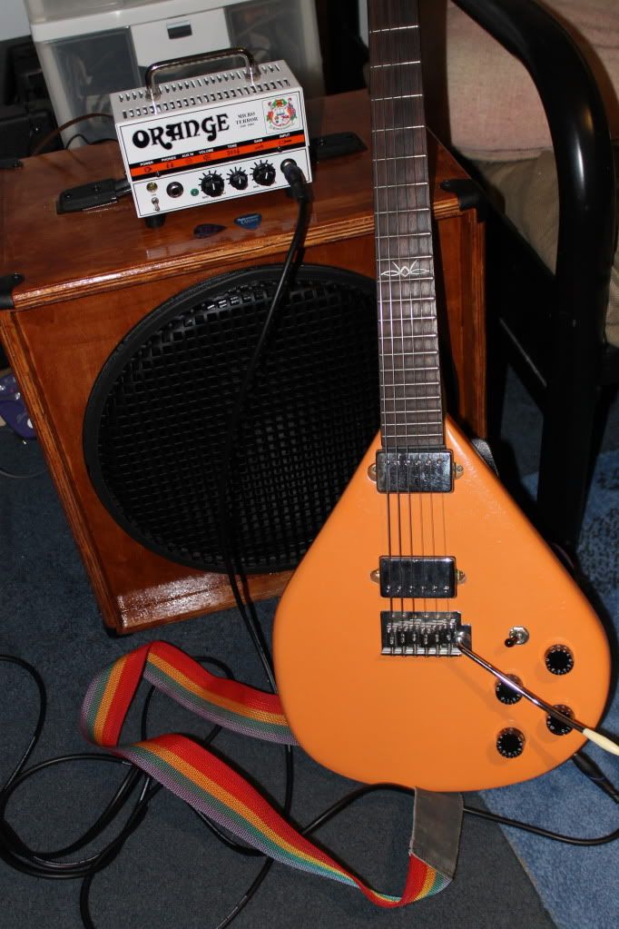 When I originally did this back in about 2009 or so, I had it wired with the "Peter Green Mod", where in the center position on the 3-way switch, the pickups are out of phase. It was interesting for a while, but several years ago I rewired it back to a standard 2-HB wiring. |
|
|
|
Post by newey on Apr 10, 2024 11:21:41 GMT -5
I'm hoping after the downsizing, you still have the electric pumpkin? The infamous pumpkin isn't going anywhere! mikecgThe Tascams I bought with the headphone amp (not sure of the model) were about the same money, about $30 USD. Can't really compare them to better headphones as I wasn't familiar with the sound of the amp, would have to use the stereo with a well-known piece of music like Dark Side or something to really compare. I have an old pair of Sennheisers that I have used with the stereo for years that I could compare these to, the Sennheisers certainly cost me a lot more money "back in the day" as they say. But these seem just fine. I wanted to get a pair of closed phones for the headphone amp and these were the cheap option. |
|
|
|
Post by newey on Apr 9, 2024 20:19:37 GMT -5
So, several months ago Mrs. Newey and I sold the house and downsized to an apartment, which we are loving. As empty nesters, we were payimng to heat/cool/maintain a whole lot of square footage that we weren't using. But as part of the downsizing process, the guitar stable was cut back pretty substantially, and several amps went as well. (The trusty old Peavey I stashed at the cabin, where I visit it and give it the love it deserves about monthly.) And, I still have the Quilter pedal amp and 10" cab in the apartment, but I can't crank it much- We now have upstairs neighbors, one of the downsides of apartment living. A new rig was needed. So, I hit up Musician's Friend for a headphone amp and a pair of headphones. I bought a Vox Amplug "AC30" and a pair of Tascam cans. Unbeknownst to me, I had a bunch of reward points from purchases I made years ago at MF, so I only paid about half of the ticket price. Anyway, got this today, my new apartment-friendly rig:  Does it sound remotely like an AC30? Mind you, I haven't played through a Vox AC in probably 35 years, but, no, I don't think it sounds like an AC30. And I still have a learning curve with this thing, the documentation that comes with it is horrible, it basically tells you to go online and download an owner's manual. Which I will do, but in the meantime, I'm toggling through effects settings without knowing what they are or how, exactly, to change them. And, being tiny, the controls are tiny and take a light touch. But my first impression is that it is pretty good at what it does. Some of the effects were underwhelming. The tremolo is good, though, that part sounded quite "Vox-ey". And the chorus effect sounded pretty good, too. I don't know if there's a true reverb in there or not, maybe I just haven't found it yet (as the instructions have zero information!). There is what sounds like a pretty boomy coliseum echo effect that I played with for a while. I wasn't able to find a gain setting that sounded very good, but again, there is more to explore yet. The clean setting sounded very sterile, like it was through a PA amp, it didn't have any of that tube "chime" to it. But again, more to come, probably. Overall, I'd have to say I'm pretty satisfied. There is apparently a rhythm function also, which I didn't play around with because I couldn't figure out how to access it. I'll report more soon, but so far I'd call it a decent little headphone amp for not a big price tag. One thing I was wondering was how the plug was going to fit different jack styles- but it rotates to do so, I can angle it several different ways in the Strat jack canoe. |
|
|
|
Post by newey on Apr 9, 2024 19:48:09 GMT -5
reTrEaD, chrisdurham- RT's diagram checks out by me, with the proviso that the white wire connects to common lugs on both switches. Where the zigzag was drawn over the series/parallel switch, it threw me at first as to whether a connection was intended there- it is.
|
|


