|
|
Post by newey on Dec 18, 2021 22:32:13 GMT -5
OK, first off, on your diagram, the volume pot is wired incorrectly. The center lug of the 3-way switch is shown wired to the center lug, the wiper, of the volume pot, and then that same lug is wired to the jack tip. Doing so wires the 3-way switch directly to the jack, bypassing the pot altogether. The center lug from the 3-way should instead be wired to the CCW lug of the volume pot, where the tone pot is connected; the center (wiper) lug of the volume pot remains wired to the jack tip. to wire the On-On-On switch, it is important to know how those switches operate: 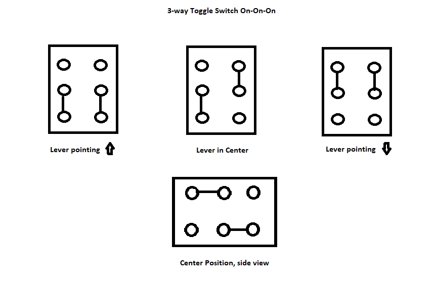 . To wire yours as jhng suggested: 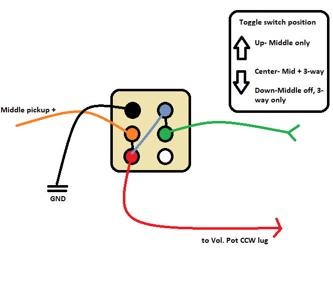 Note that the black lines designate the internal connections in the center position, for your reference. Also note that the position of the toggle lever is opposite of the lugs that are connected, so when the lever is "up", the bottow pair of lugs are connected, and vice versa for the top lugs. |
|
|
|
Post by newey on Dec 18, 2021 21:55:21 GMT -5
OK, I'll check 'em tomorrow. My matress is plaintively calling me at the moment.
|
|
|
|
Post by newey on Dec 18, 2021 11:48:21 GMT -5
I assumed it was an on off, but may be wrong. I'd assume the opposite with 6 lugs, but there are On-Off ones with 6 lugs, they just use the same framew for both types and omit the internal connectors on one side. But you should check it to be sure, assuming you have a multimeter or continuity tester. If it's an On-On type, you have more options than if it's an On-Off. But, I'm with jhng. Get a 3-position DPDT On-On-On switch so you can have middle off, middle with the 3-way selection, or middle alone. Switches are cheap.  |
|
|
|
Post by newey on Dec 17, 2021 16:09:32 GMT -5
The sweep is the full range. There is no detent. It's just a regular dual-gang pot, not a blend or pan pot. JohnH's "Strat with 2 Volumes" uses a dual-gang tone pot as a "master" tone, so as to isolate the individual volume controls, that type of application is one of the main uses, and having the DPDT added just opens up more possibilities. I'm using one (without needing a P/P one, just a dual-gang pot) in my long-dormant stereo Tele build, so as to isolate the 2 channels from one another but still have a single knob to turn (it's a Tele, so real estate on the control plate is at a premium). Of course, one could wire this up with one gang reversed from the other so as to make it a sorta-kinda blend pot, but as you note, resistance in the center is the downside. EDIT:Another thought is that of using a regular pot to, for example, blend a neck pickup into a bridge pup (as opposed to a blend pot blending one out as the other is blended in). Here. with 2 gangs and a DPDT switch to play with, I can envision wiring one gang to blend the neck into the bridge, wiring the other gang to blend the bridge into the neck, and using the P/P to switch between the two. Or maybe we blend the neck into the output of the 5-way switch with one gang, blend the bridge in with the other, and switch between the two wirings. Just spitballin', y'understand?  |
|
|
|
Post by newey on Dec 17, 2021 14:20:41 GMT -5
For years, as far as anyone knew, no such part existed. A few years back, mention was made of ordering ones from China through Alibaba or whatever. But still pretty much rara avis. But now Bourns has them, readily available at Mouser.com. They have both 500K and 250K, with knurled shafts (they may have straight shafts as well, I didn't look further). These are A taper. I ordered a pair without really having a plan to use them, they'll go in the parts bin for future reference. 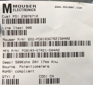 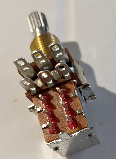 |
|
|
|
Post by newey on Dec 17, 2021 10:05:34 GMT -5
Well, report back on how it sounds. Despite the claims the manufacturers make, I'm always skeptical of things with small speakers.
|
|
|
|
Post by newey on Dec 16, 2021 21:11:38 GMT -5
Had never seen nor heard of one until you posted the link. It looks like it has some cool features, I like that the amp has an onboard charging dock for the wireless transmitter.
|
|
|
|
Post by newey on Dec 16, 2021 6:31:36 GMT -5
easonsclassics- First question is to ascertain what types of switches these are. The "mini switch" could be one pole, two poles, On-On, On-Off. What type is it? If you are unsure what type it is, how many lugs are there that you would solder onto? "3-way LP switch" usually describes a standard LP-type of switch, used for 2-pickup LP-type guitars. But on its 3-pickup LPs, Gibson used a different type of switch. Now, you didn't say if this was actually an LP (or LP-style) HHH guitar, but if it is, the switch may differ. @angellahash has a good idea for the "middle on", but whether it is possible with the switches you have will depend upon what types they are. Other options, again depending on the type of switch, might include cutting one or two of the HBs to single coil, or putting one HB in series with the others. An on-off, or "kill switch" is easily done if that's really what you want- and pretty much any type of mini-toggle switch would work for that. While there are some fancy types of switches that can get expensive, mini-toggle switches and LP-style switches are fairly cheap. We get essentially 2 types of inquiries here. Some folks ask: "Here's what I want to end up with, what parts do I need to do that and how do I wire those parts?". Others, like you, ask: "I have these specific parts, what can I do with them?" Those types of queries are less focused, and we can tend to go off in many different directions with various suggestions. It is probably more fruitful to decide what you want the guitar to do, and if the particular switches you have aren't suitable to do that, well, switches are cheap.
|
|
|
|
Post by newey on Dec 15, 2021 6:31:02 GMT -5
You're the only one I know of who has used analyzer software. I just draw diagrams with MS Paint, others use different things.
We have many members who come here because they are doing a single project, and they want a "paint-by-numbers" approach. One of us draws up a diagram for their project, someone else checks it over, and the member then solders it up according to the diagram. They don't need to know how it works or know any electrival theory, they're just following directions. And that's fine, typically after they've done their project, we never hear from them again.
But if it's going to be more than a one-time thing, it is helpful to be able to know why a circuit works (or doesn't). If any troubleshooting is necessary, it's pretty tough to do if one doesn't know how and why things are wired they way they are. And the limitations of the internet make it hard for us to help much with troubleshooting, where often a simple look at the wiring with the guitar in hand would disclose the issue.
Before I joined here, I had no idea how to read a schematic. And, while I can now read a schematic for simple circuits like a guitar, schematics for things with transistors, IC chips, etc are way beyond my limited capabilities. It just takes some time to learn. The starting point for schematics is to realize that a schematic diagram just shows how things are electrically connected to one another, it has nothing to do with how components appear physically or where they are physically located. So, for example, on a schematic the two poles of a single switch might be depicted on opposite sides of the diagram if that's where the two poles need to be to simplify showing their connections- we don't care where the parts of the switch are physically located, just how they relate electrically to other components. And one must of course learn the standardized symbols for the various components. Like anything else, start with simple schematics, learn to trace the connections.
All of us here started somewhere, we just started earlier than you. And, while some of our members do have degrees in engineering and/or years of hands-on experience, it isn't necessary to understand simple circuits like those in a guitar.
|
|
|
|
Post by newey on Dec 14, 2021 6:20:38 GMT -5
im alittle confused on blenders and balance pots. other than being dual gang how is a balance pot different? You can use a regular single-gang pot for a blender. The diagrams we were working through with you for this all showed the blender as a single-gang pot. The difference is in how you want to do the blending. With a single-gang pot, you are blending one thing into another. So, if the single gang blender is on the neck pickup, and you have the bridge pickup selected, the bridge pickup's level is fixed and you are blending varying amounts of neck signal into the bridge signal. With a 2-ganged pot with a center detent, you are blending one thing out at the same time you are blending another thing into the signal. So, if a dual-gang blender is on the neck and bridge pickups, both pickups are "full on" in the center detent. As you rotate in one direction, one gang of the pot blends the neck out; in the opposite direction the bridge is blended out. Both levels can be varied, not just one. At one extreme of rotation, it will be "all neck", at the other extreme, it will be "all bridge". Dual-gang pots without the center detent can also be wired this way, but the center detent makes it less "fiddly" in use.
EDIT: Oh, also you should read this: ChrisK's Blend and Pan pots |
|
|
|
Post by newey on Dec 13, 2021 9:48:45 GMT -5
Is there a test I can do on my multimeter to test which finish wires go to which coil? Assuming these are 4-conductor (plus shield) HBs, then yes. Set your meter to 20KΩ (if it isn't an auto-ranging model). Connect one lead to the black wire. Test the other three wires (not counting the shield). 2 of the other three will read infinite resistance or "out of range", depending on your meter. The one that is the other end of the black coil will register the DC resistance of the coil. Then, to double check, test from the green wire to the other three. This test won't tell you if the 2 coils will be in-phase or not, but if the mfr. told you that the black was "hot" and green was ground, the coils are presumably in phase when wired that way. |
|
|
|
Post by newey on Dec 13, 2021 9:38:05 GMT -5
|
|
|
|
Post by newey on Dec 11, 2021 21:45:39 GMT -5
but i swear he wants to split both coils run them through the rc circuit to shape the tone then link them in series so they are both acting as a single coil That's not what frets said, she means the RC filter could be either in series with the split coil, or in parallel, but she's still splitting coils. |
|
|
|
Post by newey on Dec 11, 2021 20:31:07 GMT -5
Splitting both pickups with one DPDT is easily done. Making it sound more like a single coil? Not so easy. Adding a cap and a resistor to the split coil will always cut some signal at some frequencies, you can't get more than you started with. A split HB coil is significantly smaller than a SC Strat pickup, that's a big part of the reason they don't sound the same.
|
|
|
|
Post by newey on Dec 11, 2021 9:17:06 GMT -5
The above- and this whole post- is one big run-on sentence without punctuation, and it is therefore very difficult to discern your meaning.
The only thing omitted from your diagram is the string/bridge ground wire. This is understood to be needed, and is omitted for clarity. The only thing going between the lugs of any pots is the treble bleed resistor and cap on the volume pot (which is optional in any event). No other "jumpers" are needed.
As to pots, if you measure between lugs 1 and 3, it should give you the value of the pot, plus or minus the 20% tolerance most pots are made to meet. Measuring between the other lugs will give varying measurements depending on where the knob is turned, and also depending on the taper of the pot. JohnH's "Tone Controls" section has more data on how pots vary as you roll them down.
If you have the guitar still wired up at present (and not working, as you said), you can do the testing exterior to the guitar by connecting your meter to the tip and sleeve of a cable. Make a table for all resistance values for all the various switch positions.
I mentioned checking the jack as it is an easy mistake to make to wire it backwards. I always have to look closely at the jack to be sure which lug is for the tip.
|
|
|
|
Post by newey on Dec 11, 2021 0:51:46 GMT -5
This may seem to be, and is, pretty obvious if one knows how the full 4 Pole Supewrswitch works. But if anyone should ever need to know,here is the skinny on the 2P5T Half Superswitch. It is literally one wafer of a two-wafer full Superswitch: 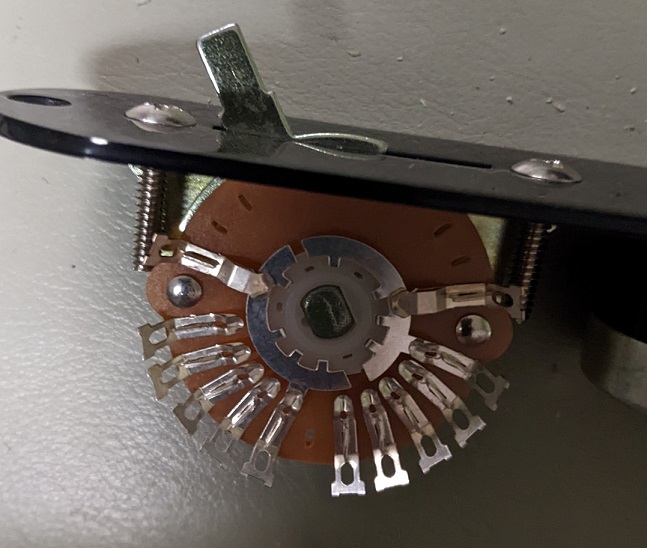  In diagrams, it can be depicted thusly:  This is a very useful switch, as it will fit into a Tele cavity without modification, and other places no Superswitch dares to go. For a Strat-type guitar, it can be wired to give the N + B at position 3 |
|
|
|
Post by newey on Dec 11, 2021 0:29:45 GMT -5
Slow progress. Got everything dismembered and got the new Bootstrap pickup installed. Shielded the control cavity FWIW. Started wiring tonight but my cheapo soldering iron bit the dust. Off to pick up a new one tomorrow . . . 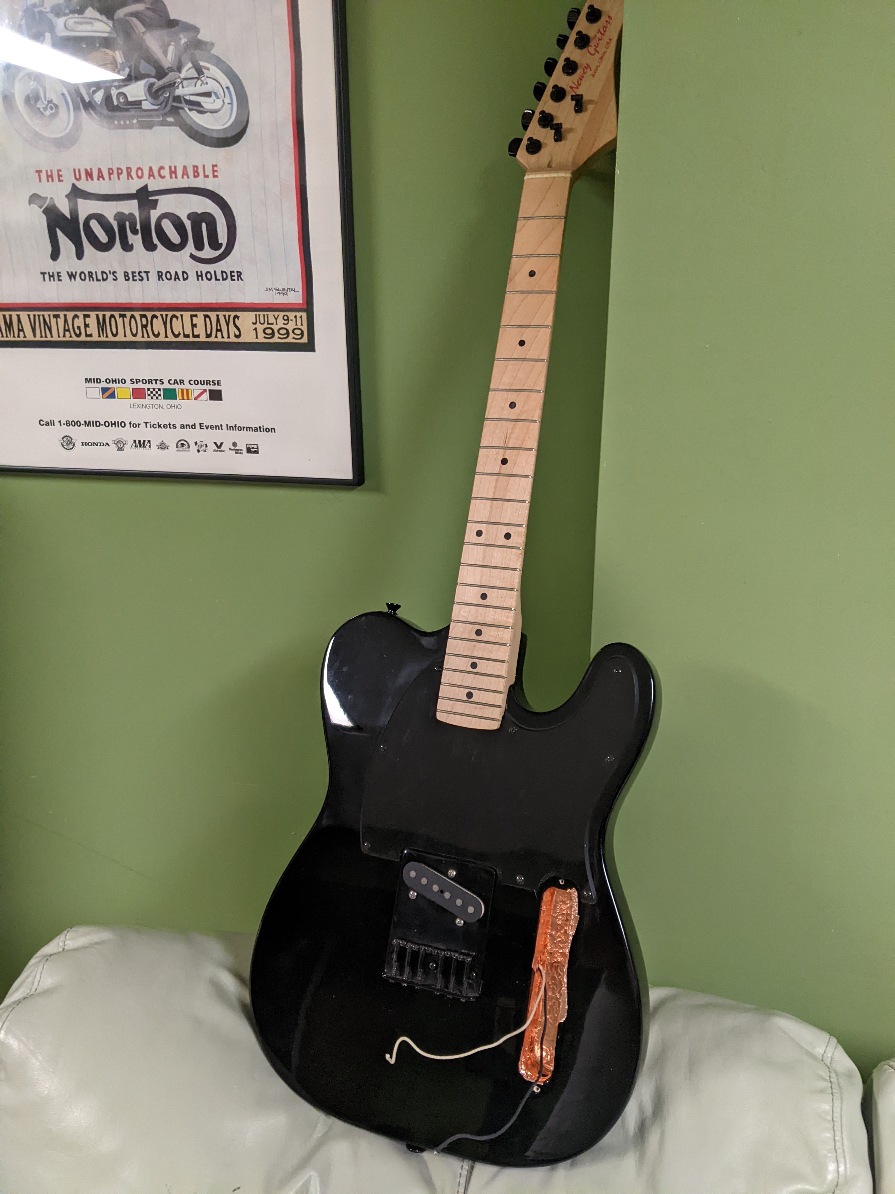 |
|
|
|
Post by newey on Dec 10, 2021 22:25:38 GMT -5
psiloguitarensis- Seems to me like you're chasing your tail a bit here. You've wired it upo, it doesn't work, but instead of troubleshooting the problem, you're starting over with new components and redoing the whole thing, when there might be only one or two things wrong. Don't assume a switch is bad, test it with a multimeter to see if it works or not. If you don't have a meter, get one. The money you'll save in new switches will pay for it. Before you start ripping wiring out, test it. Does it have 3 positions or only 2? Assuming it has 3, test it. Try removing it from the pickguard. If you get 5 positions with it unmounted, then the slot in the pickguard is too short. If it still won't go into position 1, then you may be right about a bent lever. If so, see if you can see where it is bent, it may be that a bit of (very gentle) pressure can bend it back. Then test the switch. Double check that you have the jack wired correctly and not reversed. And if you haven't yet taken my advice to remove the shielding from the jack area, I'm still recommending that.
|
|
|
|
Post by newey on Dec 10, 2021 9:37:00 GMT -5
A kill switch makes sense too. I usually think of that for stutter effects and such, where you wouldn't want to put it on a push-pull. But I can see the appeal if only when sitting it on a stand during a break or something. Even when I use a headstock tuner, I have a pedal tuner on my board essentially as a mute switch for that reason. Not exciting, but useful. I have a late-'60's Univox semi-hollow body, sort of like a ES 335 clone with some Gretsch-ish features as well that has a "kill switch", but back when the guitar was made, they called it a "standby switch" for just that reason, so you could leave it plugged in onstage. As for the active possibilities, getting a 9V battery into the F-hole may prove easier than getting it out again. . . . |
|
|
|
Post by newey on Dec 10, 2021 6:24:12 GMT -5
but something not working right If you want our help troubleshooting the problem, we'll need more specificity. What exactly is it not doing? |
|
|
|
Post by newey on Dec 9, 2021 23:20:24 GMT -5
ninethirty- I couldn't recall whether I had appropriately welcomed you previously, so better to be duplicative than omissive: Hello and Welcome to G-Nutz2!All of the following is just my not-so-informed opinion, so grain of salt and all that. - I think the switchable tone cap thing is overblown. Minimally useful IMO. - Phase, yes you'd have to dewire/rewire the connection to the covers. Whether it's useful or not I guess depends on how much of a fan one is of OOP sounds? - A "sorta Varitone" type of circuit would have some appeal. 2 push/pulls could give basically 3 options (with the 4th position a bypass) So, your other P/Ps would be wired to cut bass frequencies, these would cut treble. Between the 4 pots, you'd have a bunch of variations. - I like the solo/blower switch idea also, but I think it works better with a toggle switch. If'n yer gonna be a'soloin', it's the flick of a fingertip to hit a toggle switch. Much quicker than using bwo fingers to lift a P/P pot up. -Active circuits opens up a whole 'nother subject. I'd vote for an onboard FuzzFace clone . . .  |
|
|
|
Post by newey on Dec 9, 2021 6:09:01 GMT -5
The LP Deluxe wasn't on her list. Probably because she doesn't play.
But I did buy the things that were on the list, including WeatherTech floor liners for her pickup and the perfume she likes.
|
|
|
|
Post by newey on Dec 8, 2021 21:03:56 GMT -5
Yes, but it may be a few days before I can draw something up for you.
|
|
|
|
Post by newey on Dec 8, 2021 16:36:51 GMT -5
im not entirely sure what i’m looking at:/ could you perhaps label the switch/ toggle? i just need more of a reference. im not sure where wires coming from/going. im a little green i will admit. First off, @angellahash's diagram is a schematic, not a wiring diagram. It is drawn using a 4-pole Superswitch and a DPDT "On-On" toggle switch He uses only 3 of the 4 poles of the superswitch; the commons of each pole are labeled "C", with the corresponding lugs numbered 1-5 for each pole. The DPDT toggle is in the upper right of the diagram, with its lugs labeled 1 through 6. The three pickups are shown as inductors (which in fact they are); these are the 3 squiggly lines at the left-hand side. Each one has a "+" symbol to indicate the "hot" line. To implement his scheme, you would need to buy a Superswitch or a Megaswitch M. These are both 4-pole, 5 throw switchs ("4P5T"). For a Superswitch, angellahash's diagram will translate directly; for the Megaswitch M, the lug assignments are differently ordered, so the diagram would still be used, but we would need to translate the switch lug labeling to reflect the differences. You stated that the switch you have is a Megaswitch "S+T". Per Schaller's website, that type is only a 3-position switch, not 5, so it won't be suitable for your needs. That Ibanez toggle switch is apparently also a specialized switch, to work with their proprietary 5-way switch; I can't tell what it's doing from your photos, but getting a standard DPDT On-On toggle is no problem, they're fairly cheap. But you would have to buy either a Superswitch or Megaswitch M, as you need at least 3 poles to do what you want (and there are no 3-pole 5-way switches, so you'd need a 4-pole one). Typically, we use a schematic to work out the details of a scheme, as angellahash has done here. Then, we translate the schematic into a wiring diagram before you actually start soldering. Often, we would ask you to draw the wiring diagram from the schematic yourself, so that you better understand what is happening with a particular scheme. We would then double check your wiring diagram against the schematic before you start in. But work from here depends on the switch you select, as above. |
|
|
|
Post by newey on Dec 8, 2021 16:08:12 GMT -5
Let me put it this way, RT- I really really love my wife, but she's not getting an LP either.
|
|
|
|
Post by newey on Dec 8, 2021 14:31:57 GMT -5
String winder? Gross of guitar picks? Strap, cables? Power supply for pedalboard? Or, if it's someone you really, really love . . .A new Gibson LP Deluxe! Santa's just thinking out loud here . . . |
|
|
|
Post by newey on Dec 8, 2021 12:03:31 GMT -5
glee-
Hello and Welcome to G-Nutz2!
I was responding to your previous post when you deleted it. You were having trouble uploading images, and I was pointing you to the instructions for doing so, which are in our Forum Info section (in "Harmonious Notes")
Your current post does clarify things more. Still, a few questions. Am I right in assuming that "p" and "s" in your list of switch positions refer to the pickup combinations being in parallel versus series? Second, in your previous post, you mentioned a Megaswitch M; now you said a Superswitch. Which one will you be using- the two types are equivalent, but the connections will differ. Also, will you be reusing the mini-toggle? If so, we will probably need some well-focused images of that 8-pin clip to which you referred.
|
|
|
|
Post by newey on Dec 7, 2021 21:36:10 GMT -5
Or not. But I take your point. cynical1 would probably agree. |
|
|
|
Post by newey on Dec 7, 2021 19:13:03 GMT -5
When I was a kid, the pedals to have were the “bear trap” style Yes, and for us wanna-be racer-chasers, you had the bear trap pedals with the metal toe clips. Mine was a Schwinn "Varsity" 10-speed. Also had the extender-levers on the handbrakes. I got the white finish 'cause that got you the cool black decals and handlebar tape- all the other colors came with white letters and tape. |
|
|
|
Post by newey on Dec 7, 2021 16:53:43 GMT -5
chman-
Hello and Welcome to G-Nutz2!
Sorry, I don't know of any pedals that clone the Watkins Copicat. A quick search found a bunch of VST plug-ins to emulate that unit, but no hardware.
Someone else may be along with a suggestion for you. I've never even seen a real Copicat, much less played through one, so I don't know much about it. My first thought was that (I think) the Roland Space Echo had multiple playback heads as well, and I know Boss makes a digital pedal to clone the Space Echo (Boss RE-20), but I don't know whether that was similar to the Watkins 3-head system you describe.
|
|


