|
|
Post by ChrisK on Dec 12, 2008 21:18:27 GMT -5
This was a post from some time back. Someone misconstrued my intent, it was just a discussion of fairly cheap (and inexpensive) tools that can be used. I still use a Dremmel tool as well.  Methods for Machining Wood Methods for Machining Wood |
|
|
|
Post by ChrisK on Dec 11, 2008 17:57:39 GMT -5
Yeah, is identical to my Sienna Sunburst one in switching functions, but is an American (U.S.) Deluxe model. The model number is 010-1500, the "010" means that it's U.S. made. The differences are that the AmDlx series have SCN pickups, have a better vibrato, locking tuners, might have a better neck feel (although the one that I have has a great neck), and mine has the ash body (a $100 adder). They're going for $1,250 on musiciansfriends.com, so they can be had for about $1,000 to $1,100 new in the U.S. at retail stores. guitars.musiciansfriend.com/product/Fender-American-Deluxe-Stratocaster-HSS-Electric-Guitar?sku=511145Some of the new Squier "classic vibe" series guitars are getting great reviews, even to the point of being considered to be better than the MIM Fender products. www.squierguitars.com/classicvibe/While not a Strat, I like this one for its pine body; www.squierguitars.com/products/search.php?partno=0303025507 |
|
|
|
Post by ChrisK on Dec 11, 2008 13:12:34 GMT -5
tedfixxI'm not quite sure which model this is. There is this one, which is HSS and has piezo saddles, but it's not made in the U.S. (it is American in that all folks that reside in the western hemisphere are in the Americas (north, central, and south). This guitar is made in Mexico (Fender numbers beginning with 013- are MIM). www.fender.com/products//search.php?partno=0139300367I have one of these with Fishman saddles (it's also MIM, 013-). The acoustic tone is ok, but my Godin with RMC saddles is better. www.fender.com/products//search.php?partno=0135000303www.godinguitars.com/godinxtsap.htmI have the Fender American (U.S.) 50th anniversary Strat (SSS) with the S-1 switch. It's a very nice guitar, but it's a collector version so I don't play it. I have the American Standard HSS in Sierra Sunburst finish (ash body) with the S-1 switch (the version before the Standard series was renewed this year). It is also a very nice guitar, especially with the S-1 switching.  Fender removed the S-1 from the renewed series, which I consider to be just plain stupid. One doesn't have to use the S-1 switch if'n one doesn't want to. (Also, tone controls are adjustable between "0" and "10", but don't tell anyone.)  The new series has; This is a good thing. Pfffft. Well, ok. Pfffft. The new Sierra Sunburst finish is exactly like the one that I have, except that it's, uh, new. (This is a concept known as marketing (or commercial fraud) that gives the impression that there actually are compelling actual reasons to buy something. It works better if it doesn't actually make sense.) Since the renewed ones were on the horizon when I bought it, I got it for about $600 new (it was normally $1,100 street). I've tried a number of the U.S. Highway1 guitars and have not found a single one that I'd buy, even at the sub $500 price that I've been offered on new ones. I find them to be overly dull sounding (and looking). I have two Strat copies that I've built. One is an all-padouk chambered guitar with DiMarzio pickups and the Mike Richardson wiring scheme (with my addition of two phase pp pots and series tone control structure). The PadoukCasterThe other is a lacewood topped mahogany body currently with the EMG DG-20 pickup set in it. guitarnuts2.proboards45.com/index.cgi?board=repair&action=display&thread=2154I have four other ones "in the oven"; a book-matched flame walnut chambered rear routed one routed for a Wilkinson and HHH pickups, 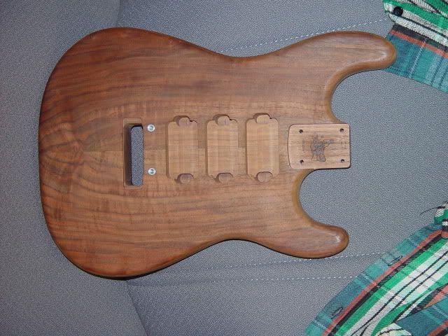 a swamp ash rear routed one with a Rio Grande Tele Twangbucker bridge, a lipstick middle, and a Duncan P-90 Stack in the neck (this is an HSH config), a koa top routed one that is an HSS config,  and a solid walnut rear routed one with a TOM/string thru bridge routed for HSS. 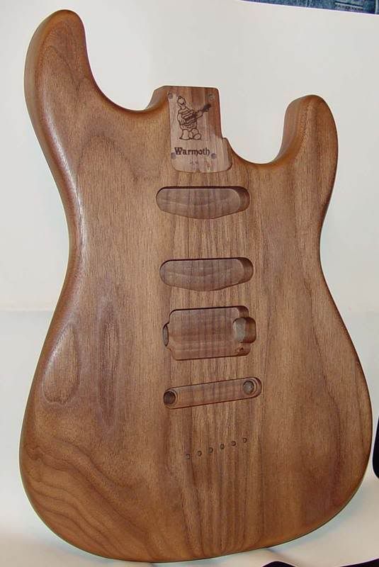 Oh, I have an idea; you could build one. 
|
|
|
|
Post by ChrisK on Dec 11, 2008 12:01:58 GMT -5
Ooooh, so you're not actually using a no-load (as in Delta tone) pot, but TBX pots.
Which TBX pot is causing the pop? Are they both causing this?
TBX 1:
250K - no load treble cut (normal tone control)
1M - bass cut
TBX 2:
250K - no load blend middle p'up with bridge p'up (for fine-tuning 'quack' position, or taking edge off bridge p'up)
1M - blend bridge p'up with neck p'up
|
|
|
|
Post by ChrisK on Dec 10, 2008 21:21:40 GMT -5
While a parallel resistor can be added, since there is no connectivity to the isolated terminal, it would have to be added across the pot from the CCW end terminal to the wiper. That being said, I'd go along with JohnH's suggestion to use a large value, but I might start with 1 Meg Ohm and work my way up. Most of the no-load pots that I've seen are 250K, so I might just replace it with a 500K "loaded" pot. A 500K audio pot is down to 250K at about "7 1/2" to "8" on a Strat knob, so in essence it goes to "12" when at "10", but still has an effect similar to a 250K pot. I never had much appreciation for the no-load concept anyway since it functions like a 250K tone control until it functions like a switch. 500K  You could also try the TBX approach. It's a 250K pot up to "5". Then it's a 1 M Ohm pot up to "10" (or so depending on the external components used). |
|
|
|
Post by ChrisK on Dec 10, 2008 19:41:46 GMT -5
What new design themes would folks a'board like to see added to the Electronics & Wiring sections? For instance; A collection of things that can be done with a DP3T Center-ON switch (ON-ON-ON). A collection of things that can be done with a SP/DP3T Center-OFF switch. A collection of things that can be done with a DPDT switch. "Fun With Pots"  |
|
|
|
Post by ChrisK on Dec 10, 2008 16:46:48 GMT -5
Well, compromise is always a three-way street.
|
|
|
|
Post by ChrisK on Dec 10, 2008 16:45:17 GMT -5
The IBM Selectric typewriter had a relay armature that was activated for every key press.
The keyboard itself didn't click, but the typewriter still sounded like an old electric typewriter. It's called marketing.
The Rolls with the electric manual shifter had a solenoid that struck a plate on the car frame as one shifted so that it still felt like a mechanical manual transmission.
Perception is reality.
|
|
|
|
Post by ChrisK on Dec 10, 2008 16:36:14 GMT -5
|
|
|
|
Post by ChrisK on Dec 10, 2008 16:32:27 GMT -5
Did you know that Las Vegas has more hotel rooms than.............................Canada?
Unfortunately, I've met several women that were made entirely out of ice.
|
|
|
|
Post by ChrisK on Dec 9, 2008 17:03:16 GMT -5
|
|
|
|
Post by ChrisK on Dec 9, 2008 17:02:28 GMT -5
|
|
|
|
Post by ChrisK on Dec 9, 2008 16:46:23 GMT -5
......the best way to make a small fortune at guitar building is to start with a large fortune.
|
|
|
|
Post by ChrisK on Dec 9, 2008 16:45:09 GMT -5
|
|
|
|
Post by ChrisK on Dec 9, 2008 9:58:22 GMT -5
Could you post some digital pics of your wiring?
|
|
|
|
Post by ChrisK on Dec 8, 2008 19:43:46 GMT -5
The purpose of the tuned port on a bass reflex speaker enclosure is to add a tuned "filter" at a frequency lower that the natural cutoff frequency of the speaker. It also enables the peaking of the bass response in the frequency range of great pleasure to those addicted to rock music.
This comes at a cost however. The speaker becomes acoustically unloaded below this enhanced frequency and can be easily damaged from excessive cone excursion. This is why many bass speaker enclosures are sealed (acoustic suspension) systems.
While one could reduce the output level this way, it will have effect on the tone of the speaker. It will also change the impedance seen by the power tube.
Why do you want to drive the power tube harder? Since the Epi VJr is a single-ended class A amp output stage, the plate current is essentially relatively constant regardless of output power (the very definition of class A). A single-ended power tube has the same circuit structure as a single-ended pre-amp tube (asymmetrical clipping/compression). As a result, aside from the power level, the clipping/compression is similar. It's just very loudly crunchy.
You may get what you want by increasing the drive to the pre-amp stage. Put a booster between your guitar and the amp and see if this is the case.
In a push-pull class AB power output structure, plate heating from current flow IS most dependent on the output power level and is a different effect than pre-amp clipping/compression.
Also, tube rectifier "sag" is only of interest in a class AB output stage. There's no "sag" in a class A output stage since the plate current is constant.
|
|
|
|
Post by ChrisK on Dec 8, 2008 19:10:21 GMT -5
Good. We had to empirically determine things. Always buy extra parts, they're usually cheaper than the petrol to go get more.  Essentially we have created a hard voltage clamp (as hard as the power diodes can tolerate). This limits the voltage under current surge to no more than 3.5 to 4 VDC. Although rated at 1 amp of average forward current, for a single half cycle surge (8.33 mS) the 1N400X series can handle 30 Amps. www.fairchildsemi.com/ds/1N/1N4004.pdfIf you look at page 2, Non-Repetitive Surge Current, you'll see that it's a fairly beefy little sucker. Just don't use it for back EMF protection for relay coil drivers, it's much too slow in reverse recovery (use a fast recovery diode). As a result, the LED (did I mention that they are crappy diodes? - they do make good fuses tho', eh) is protected from having to handle the current surge. |
|
|
|
Post by ChrisK on Dec 7, 2008 23:09:10 GMT -5
Yes. No. These two sentences are in agreement.  There is no positive and negative end to a diode. Depending on the application, either end might be connected to either. The band marks the cathode. The other end is the anode. Anode-----| >||-----Cathode For current flow (which is unfortunately defined as the opposite direction of electron flow), if the anode is more positive than the cathode by the voltage (conduction) drop of the diode, current will flow in the direction of the arrow (>). In both of these amps, the foot switch common wire is at amp ground potential, and the signals that are switched are negative voltages. So, in our case, the amp ground is the most positive voltage. This is what the new circuit does. |---|LED>||---|51 Ohms|---- to channel select input | |---|>||-----|>||-----|>||----- to channel select input Each 1N4004 has a forward voltage drop of about 0.7 VDC. Three of them should be about 2.1 VDC. If the current thru them is very small (except for the surge current), they may not develop enough of a drop to allow the LED to turn on (it has a forward voltage drop of perhaps 1.8 VDC. The fact that the LED flashes seems to indicate that except for the surge (turn-on) current event, insufficient voltage is being developed across the LED. The simplest thing to do is to add a fourth diode in the three diode series string. This will develop 2.8 VDC max (or less as we seem to see). |---|>||-----|>||-----|>||-----|>||------ The series string forms a voltage clamp in that the drop across all four is limited to perhaps 3.5 VDC at the surge current of an amp or more, limiting the maximum current thru the LED. Once the surge current is dissipated, the LED and 51 Ohm resistor conduct the current. A little more fishing and trial and error are in order. Remember, I'm doing this with posted schematics of unknown vintage that may well NOT match either amp, and have no data regarding the LED, internal amp channel select relay, or actual currents occurring. |
|
|
|
Post by ChrisK on Dec 7, 2008 21:38:05 GMT -5
No, 200 Ohms in parallel with 510 Ohms is 143.66 Ohms. This is within the tolerance on your 150 Ohm resistor, and would be virtually the same.
See how bright the LED is with no parallel resistor. Then try a 510, and then a 200 Ohm one. If you have a 500 pot, you could dial the resistance that you want for the brightness that you want.
I have no way to predetermine the brightness since I can't see that far (and have no data on the LED).
Did you indeed use 1N400X series diodes?
|
|
|
|
Post by ChrisK on Dec 7, 2008 20:31:12 GMT -5
|
|
|
|
Post by ChrisK on Dec 7, 2008 20:16:08 GMT -5
OK, so you've shielded the wiring cavity where wires have few turns afoot. Did you shield the pickup cavities where inductors, each with about a mile of really fine wire that is tightly wound into an antenna loiter? The pickups pickup much of the noise (that mile of wire thing). Shield each pickup cavity in the body and run a connected wire from each back to the star ground in the wiring cavity. If it wasn't the single coils being the culprit, the humbucker would never have been invented.  You mention that you have conductivity between the parts of the shield. Do you have conductivity (less than a few Ohms) between every part of the shielding? This might help, it's for a Strat Jr. The pickup selector might be different, but the general layout will be similar. www.fender.com/support/diagrams/pdf_temp1/stratocaster/0133800A/SD0133800APg2.pdf |
|
|
|
Post by ChrisK on Dec 7, 2008 20:05:30 GMT -5
That's why we can't completely ban smoking, it's how they keep Keith inflated.    |
|
|
|
Post by ChrisK on Dec 7, 2008 12:02:03 GMT -5
Happy birthday. With it being this close to Christmas, you're lucky when you get something other than just one of your Christmas presents early. My wife knows, she was born on Dec 19!     |
|
|
|
Post by ChrisK on Dec 7, 2008 11:57:38 GMT -5
I'm glad that you see the plumbing now.
Uh-oh, now I know where you are. Oot there in Wisconsin, eh. Ya outta have aboot 2 feet of snow by now. (I can talk this way since my Mother is 1/2 Sweeedish.)
Well, my company Has a big presence in Minneapolis, but I only get to Wisconsin when someone makes a driving navigation error (we're in Wisconsin Sparky, you really did go the wrong way, eh).
I love the roads around Minneapolis; where else would you have 35 West (which goes North and South) AND 35 East (which goes North and South), and they are NOT related.
|
|
|
|
Post by ChrisK on Dec 6, 2008 22:26:38 GMT -5
Montecristo #2. Cohiba Robusto. And not that there interloping Dominican knock off stuff either. I have a set of J pickups. Actually I have four of them, two that came in SD boxes (I don't know what this means, but I have Fender covers for them) and two that are Quarter Pounders. I got these when I bought a brandy new Squier P Bass special for $50 at a GC blowout sale. I got the pickups used and then sold the bass for $150 the next week. Then I bought the Stu Hamm Urge II for less than $800 brand new (they were $1,280 street at the time, I had to buy it). You could do something like this; Two Many Pickups.But not in pink fer God's sake.  |
|
|
|
Post by ChrisK on Dec 6, 2008 21:59:51 GMT -5
Wolf's image is not wrong. The way that you connected the output jack "tip" to it is wrong. To use Wolf's drawing in your guitar, what he calls "From volume control "hot" lead" is connected to the output jack "tip" terminal ( Out bus). This is a circuit that is in parallel with the output jack. He calls it this because this circuit is usually connected on the other (pickup) side of the volume pot. The output jack "tip" terminal also is connected to the center terminal on your new pickup selector switch ( Out bus). 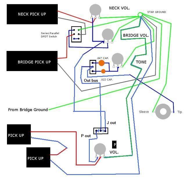 |
|
|
|
Post by ChrisK on Dec 6, 2008 18:45:08 GMT -5
You can use;
1N4002
1N4003
1N4004
1N4005
1N4006
1N4007
They're just higher reverse voltage versions.
|
|
|
|
Post by ChrisK on Dec 6, 2008 13:31:54 GMT -5
The wire from the output jack "tip" goes to the wiper on the tone pot. I believe that this is incorrect and that it should go to the center terminal on the tone switch.
We will divide the circuit into two sections; the first is the J pickups, their series/parallel switch, and their two volume pots. There is a wire that goes between the left terminals on both volume pots (in your drawing), which we will call "J out". This is the output signal from both and it also currently goes to the center terminal on the tone switch.
The latter is the connection that will be interrupted by the new selector switch.
The second is the output jack, the tone pot, and the tone cap switch. We will call the connection to the output jack "tip" and the center terminal of the tone cap switch the "Out bus".
There is a new third section for the P pickup. I'm not sure that you should switch the P pickup into parallel. When just one string is vibrating over one coil, nothing is occurring in the other coil and it will appear as an inductor with a few thousand Ohms of impedance to ground and likely will attenuate the signal. You should hand twist the coil wires into parallel and test this before you commit to a separate switch for this mode.
This section is comprised of the P pickup and its volume pot, wired as the individual J pickups are wired to their respective volume pots (when in parallel). The "left" terminal of the P volume pot will be called "P out".
The new group selector switch (you will have to let me know what selection sequence you want since this determines the switch type) will select between section one, both sections, or section two. The common terminal on this switch goes to the "Out bus". Section one's "J out" goes to one selected terminal and section three's "P out" goes to the other.
Yep, this will use a DP3T ON-ON-ON switch.
Now, if you're willing to have the modes organized like this;
2 J-bass on
All three on
1 P-bass on
you can use a plain old LP-style selector switch (or a DP3T ON-ON-ON).
|
|
|
|
Post by ChrisK on Dec 5, 2008 23:55:55 GMT -5
The three extra diodes form a 2.1 volt clamp. The 51 Ohm resistor in series with the LED limits the surge current thru it. 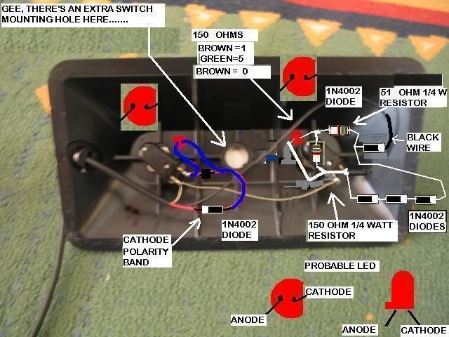 |
|
|
|
Post by ChrisK on Dec 5, 2008 20:50:12 GMT -5
Yeah, but let me run a simulation to characterize things.
|
|