|
|
Post by ChrisK on Nov 11, 2008 16:13:39 GMT -5
Well, I guess it depends on where your picking hand tends to loiter.  I tend to loiter near the bridge. Touching a floating cover/signal wire is touching a floating cover/signal wire. |
|
|
|
Post by ChrisK on Nov 11, 2008 13:54:35 GMT -5
So it was like a speed bump or a curb and this is where you fell?  If you eliminate the tone pot, you do have some interesting options. You could use two volume pots alone, or you could use two push pull pots for the volumes. Hmm, there be switches attached. What could we use them for? I know, to switch in a tone setting. If you almost never use the tone, have one setting do nothing (or select a 240K resistor in series with the existing tone cap) and the other a resistor value equal to the tone pot setting when you actually aren't almost never using it. In other words, you could have four tone settings (two switches - four combinations) a la' the Gretsch tone switches. Now, here's a possible fly for your ointment; do these pickups have a single conductor plus shield wiring? If so, there may be some issues with series and reverse phase wiring (one pickup's shield and metal cover will not be grounded, but connected to the output (reverse series), or the other pickup's output (series)). Either way, touching the pickup's metal cover will generate some interesting "buzz-tones". |
|
|
|
Post by ChrisK on Nov 11, 2008 13:33:12 GMT -5
Great! If anything (other than getting your long efforts to fruition), you now have a functioning base of reference guitar wiring 101 to build on, in both understanding as well as possible future mods. As I had suspected about the "handiness" of things, I also suspected something about you from your posts; that this was more than just a cry for help (or diagram). You now "know" and "see" things from a higher level. Please forgive my approach, it isn't always optimum, but there are occasions when I suspect that it is. We await the progression to interest in wiring 102....  Suspect the obvious! Check the parts list on Fender guitar drawings (at least they have the uncommon courtesy to publish parts lists as well as generally good drawings). How do I know what I know about blend vs pan pots? From the study of many Fender part lists, many "themes" became obvious. I can easily "see" how the mirror-imaging happened. A drafter said "I need to make a left-hand Strat wiring drawing. The (sub)boss said " just flip the orientation of the right-hand one over. The drafter flipped everything. Now, an interesting exercises might be to try several LH Strats of this vintage (Mexico), and see if they work properly (RH rotation) or are GeFooey (as you experienced). Bear in mind that the posts on the Fender site are not necessarily manufacturing build drawings, but "customer convenience" drawings. As one desires to consider left-hand pot response (that pan pot thing), one can refer to the "base" understanding and easily discuss only the incremental technology involved. Well, you can use a pp pot to add the neck in, but you don't need to lose a tone control function. The pp switch could use one pole to switch the neck to always in (or LH blended by the reuse of the neck tone pot), and the other pole could switch the bridge (or middle) tone to master (always in). This is fairly straightforward. Another use for a pan pot is in pickup blending such as the neck (or bridge) "blend-in" use for a tone pot. For best blending one has to turn the pot the wrong way (for the right of hand). Using the correct element on the pan pot makes this work right(handed). (An observation that is generally obvious to none.) In my Bro-in-law's Strat this past spring I put a push pull pot in the bridge tone control for one of the tone controls. I put a pan pot in the neck for the other. The pp switch did a couple of things, one of which was to switch the pan pot from being a neck tone control to a neck blend-in pot (the "right-hand" resistive element worked for RH tone and the "left-hand element worked for RH blending). (The other thing was a master tone.) I don't have a drawing specifically for this since it also included a variation of my 3 Single Coils and The "S-None Switch" design. I generally always use a 500K audio taper for tone since it's already down to 250K at around "8". The knob at "10" has the brighter tone of a knob at "12"!  |
|
|
|
Post by ChrisK on Nov 10, 2008 18:44:41 GMT -5
There are two kinds of blend pots; the first are the pan pots sold as blend pots, and the second are the true blend pots used in active bass guitars. Blend and Pan PotsIn either case, you would be able to blend between both pickups to varying degrees, but have no overall control of the volume. I might suggest that you use a dual concentric shaft pot such as the EP-4586-000 for two volumes in one. This way you can still adjust the relative level and the overall volume. Using individual volume pots with the T-Riffic will require some redesign. I recently did a design that does what the T-Riffic does but with two volumes and two tones. It also had two push pull switches per pickup for coil selection. While considerably more complex than what you need, I'll link to it since, if the push pull coil selection stuff is removed, it shows how I use individual volume pots in a series/parallel switching structure. P-Rail Switching SchemeIf you don't "see" how to reduce this for what you want, let me know and I'll modify the drawing since it's much easier to take stuff out than to add it in. Also note that I use a different combination sequence than John A. I feel that tonally, the N*-B belongs next to the bridge selection and the N*B belongs next to the neck selection. Anyway, the ordering is arbitrary. |
|
|
|
Post by ChrisK on Nov 10, 2008 18:03:27 GMT -5
Hmmm, I'd be tempted to trade and buy. You should get perhaps half the street price for the one that you have now. Things kind of suck now for the instrument market (not the firearms market, mind you) so it may be less than half.
You're likely looking at a $200'ish spend with trade-in.
The Bigsby vibrato will cost you about $100 (ebay) to $150. Then there's the labor.....
It should be possible to do this oneself, but I've never done so I can't speak to the procedure (I'll bet it's on the web).
|
|
|
|
Post by ChrisK on Nov 10, 2008 17:54:36 GMT -5
For mice I use the plastic resettable traps. I've found that I need to anchor them with nylon cord (mice will eat organic string) as the victim tends to wander off whilst "engaged". They're very easy to deal with; I just open the trap over a waste bag and then place it "back in service". For larger vermin I use the "Havaheart" spring cage traps. For ground hogs, a rag soaked in ammonia stuffed into the burrow works well. They move on. Not having a garden works wonders.......  I have made repellers using a tweeter and an audio oscillator (not formal test equipment) at about 22 to 40 Khz. If you have dogs, they will notice these. Of course, I first made these for dogs.....A neighbor had dogs that were put out at 7 am and barked forever. I set my oscillator to go on at 3 am..... I used an LM386 audio amplifier IC and a Mr. Coffee coffee pot timer (these were a few bucks at every surplus place 10 years ago). www.national.com/ds/LM/LM386.pdf |
|
|
|
Post by ChrisK on Nov 10, 2008 17:36:15 GMT -5
Whoa, no. It was a tongue in cheek way of implying (after the discussion of WHY the pots didn't work correctly for you) that with linear pots, mirror imaging the wiring would work the same as right-handed, the knobs would just turn the other (left-handed) way.  (clue)  ;D ;D (it's funny)  (well, not that funny) Aha, indeed. The pot sold as a blend pot in this industry (which is actually a mixer pan pot) contains a right-handed and a left-handed audio taper element. This means that it can be used in place of either audio taper. You just have to choose the correct element. You can use a blend pot for both tone controls as well as the volume. Yes, for you, but not for me. I don't have wiring diagrams for the standard configurations and "standard" mods at hand since I have no need for them (and they are all over the web). Finding the correct parts on various web sites takes time. Drawing a wiring diagram takes time. One then has to pour it and post it and link to it. I can type a lot faster than I can draw. Part of the conversation is biased towards determining the level of technical understanding and the response needed. It is in my interests to minimize the amount of time that I spend, as well as to find others to join this group and its discussions, at various technical levels. Summary: If you want to use the right-hand pots that you have, use the right-hand wiring diagram. If you want left-hand knob rotation (mirror image from right-hand) use blend (pan) pots and the left-hand wiring. You'll have to determine the correct element ( I honestly don't know which is which). It's the one with the opposite taper response as the right-hand pots. Apparently I DO know how pan pot elements are arraigned. I took the step of referring to our "Schematics" section and found a post related. Electronics TemplatesThe third drawing down has the schematic representation for a pan pot on it. "10" refers to clockwise (I'm correct-handed)rotation.  |
|
|
|
Post by ChrisK on Nov 10, 2008 9:46:23 GMT -5
You have it in mind, but need to see it. a blend pot ....... which are not. Pan away. I could, but, these mods abound a'web. Visit the Stew Mac and Seymour Duncan sites. The Strat already has a master volume. Remove the (now) master tone circuit from the 5-way switch and attach it to the hot end terminal of the volume pot. A pan pot to blend in (well, in this case it IS blending in) is just a series connection from the pickup to be blended in to the hot terminal on the volume pot (or 5-way switch). The standard pan pots sold as blend pots will solve your handed problem (you won't have to rewire) as well as do the blending function. You'll have to fix the knob knumbers yourself.  |
|
|
|
Post by ChrisK on Nov 9, 2008 23:14:19 GMT -5
|
|
|
|
Post by ChrisK on Nov 9, 2008 22:04:33 GMT -5
Uh oh, what does this mean? I'll take a look at the Fender drawings. ;D ;D ;D ;D ;D And I have. You've been bushwhacked by the "handedness" of things guitar. The "Left Hand" wiring arrangement (  ) that you mentioned is too true to be good!  Some might call it marketing. While the wiring to the pots is indeed reversed (mirror-image) between the two wiring diagrams, the pots ARE NOT. Both 013 MexiStrats that you reference use the 0013446000 250K audio taper pot. In both right-handed AND left-handed guitars, these are right-handed pots. Furthermore, the 5-way switch terminals also are mirror imaged from the right-hand to the left-hand guitar. Both use the same 0053291000 switch. 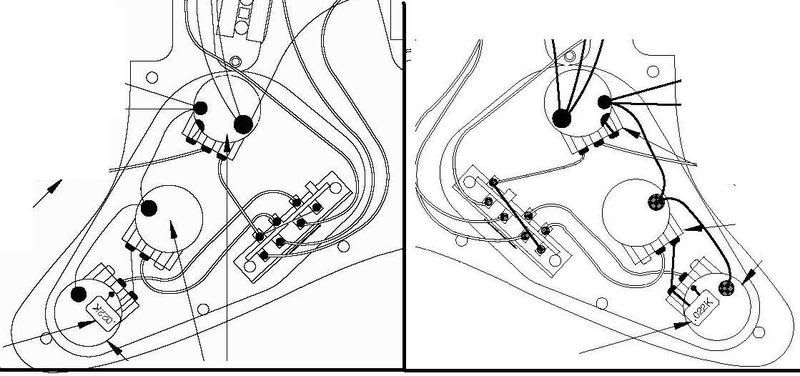 When one connects audio taper pots backwards it makes linear taper pots look real special. Your pots are wired backwards. Your switch is likely wired ok. Some fart-for-brains in their drafting department just mirror imaged the drawing for the left-hand guitar. This would work fine if the pots were left-handed (reverse audio taper). (It wouldn't hurt if there were reverse-numbered knobs too.) (I remember when d'afting departments actually checked drawings prior to publishing them.) You will have to follow the right-handed wiring for the pots. BTW the left-hand guitar shows the switch correctly, the right-hand guitar drawing is incorrect in the terminal positioning. If one followed the terminal sequence wiring order for the right-hand drawing of the switch, it would still work. If you'd had the sensibility to use linear pots to begin with, this wicket wouldn't be sticky.   ;D ;D  OK, I said that I had a way around right-handed pots, pan you see it. If you want to know more, let me know. |
|
|
|
Post by ChrisK on Nov 9, 2008 14:21:32 GMT -5
You betcha'!  One wouldn't want to be inadvertantly a'togglin' when they was aimin' to be advertantly a'switchin'.  Unlessin' they's a female member of the population, and then they'd still be a'togglin' even after they'd a'switched.  A'togglin' is what they do. A'switchin' is what we do (and why we're always a'wrong.)  (Or so I'm told.)  |
|
|
|
Post by ChrisK on Nov 9, 2008 13:56:48 GMT -5
Some questions come to mind. First, a simple but not always obvious one. Are you left-handed and turning the pots backwards as compared to a right-handed operator? If you ARE left-handed and want controls that turn backwards (CCW is "10"), I do have a simple electronic solution for this, but you're on your own concerning the "knob knumbering". Why do you believe the 250K pots are linear? Yes, it will affect the overall brightness at the full-off rotation of the tone control as well as the loading effect of the volume control. A neat practice is to always use a 500K pot for tone. It will be at 250K at around "7-8" and be at "12" (brighter) when full on.  The taper (linear or audio) is the rate of change of the pot when rotated. This affects the rotational response of the control. I always test every component that I use. They're easier to just not use than to unsolder and replace. Test the pots. Measure the end terminal to end terminal resistance. Write it down and on the pot side with a black Sharpie marker.  Set the pot to exactly half its rotation. Measure the resistance from the wiper terminal to EACH end terminal. If it is Linear, you will read about half the end to end resistance on each side of the element. Linear pots are often marked with a "B" for taper, but this varies. If it is Audio, there will be a substantial difference (around 5 to 1 or more) in resistance on each side of the element. Audio pots are often marked with an "A" for taper. Write an " A" or " L" on the side of the pot.  A linear taper volume pot turned from "0" to "2" has the same resistance ratio as an audio taper pot turned from "0" to "6". If the volume pot, when turned clockwise from "0", turns on abruptly, I suspect a linear taper. A similar effect will occur for a linear tone control. The tone changes will occur abruptly and then not change much at all. There are those a'planet that claim that linear controls are better for volume and/or tone, but I suspect that this is related to the blatant overuse of a Marshall full-stack over extended periods of time. My 85 year old Father-in-Law calls this effect "Huh, eh?"  |
|
|
|
Post by ChrisK on Nov 8, 2008 22:44:40 GMT -5
I'm not sure that it's all that coil switching and "Nutz" stuff that we find so compulsive.
The digital guitar is something that they've been working on for several years. It uses a deterministic Ethernet-like approach to multiplexing the individual 6 strings as well as the overall audio output to a distribution box as well as an audio channel back into the guitar. I saw this demo'd back in 2003 at the consumer electronics show in Las Vegas and couldn't see why anyone cared at that point (few did).
It would appear that a better user interface (UI) is now built into the "knob" that controls stuff. Combine this with the technology of the robot guitar and you have the new thing.
It looks like you can set the pickups and coils selected as part of each tuning setup, so when you change the tuning (or setup) everything follows along. If so, the LP three-way switch is merely a "suggestion" to the electronics.
It attaches to an external elextronics box.
|
|
|
|
Post by ChrisK on Nov 8, 2008 21:50:09 GMT -5
Knob knob? 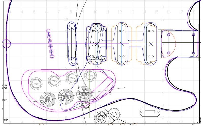 |
|
|
|
Post by ChrisK on Nov 8, 2008 21:36:23 GMT -5
I've taken the path of proving the possibility of a complex design before I draw a trace. By knowing the possibility of success (or at least the minimum number of poles and positions), I can at least get into the right ballpark first.  My focus was on the minimum number of poles on the secondary switch (it was a challange to beat 8 poles after all). One could revisit the analysis to see how a 4PDT decreased those hanging about. Also, one could revisit for shorting any hanging coils when not selected. I drew up my design in AutoCAD. It works as the analysis indicated. 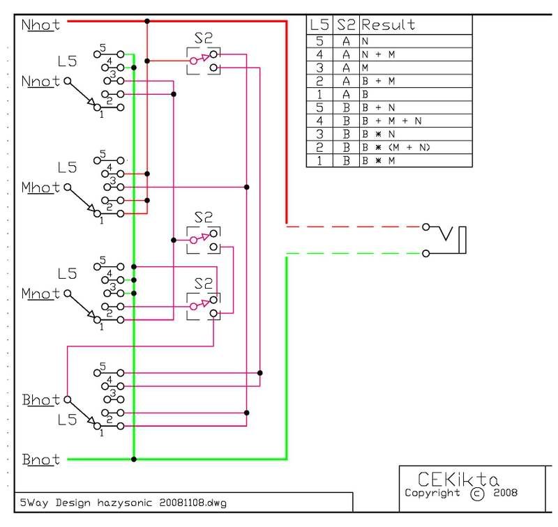 Proof is. |
|
|
|
Post by ChrisK on Nov 8, 2008 0:32:07 GMT -5
Please keep in mind that the order that you want things in may adversely affect the ease of how you may actually have things realized. pathLet's start with the same pole assignment on the 4P5T lever switch. We have four poles; we'll assign one to Bhot ( Bnot is locally grounded), one to Mhot, one to Mnot, and one to Nnot ( Nhot is connected to the output). With this structure, we can trivially do any parallel combination since we determine where each of these four leads go (in a simple one dimensional parallel structure the choices are no connect, and either output or signal common. Let me make it clear that I am not calling anything "ground" since no lead coming from a pickup is EVER a ground except for a shield connection which needs to be locally grounded. These are AC generators with two leads, one is only ever ground if we externally connect it to ground. In any series structure, all pickups CANNOT have a "ground" lead since all not-HOT leads are not connected to ground. In a series structure (two dimensional), these leads go to other places in addition the those mentioned for parallel. Realizing any collection of combinations on a 4P5T switch thus assigned is trivial. In fact, every possible combination (for three single coils, 17 excluding OFF and phasing) is possible except M*(B+N) which requires 5 poles since Bnot or Nhot must leave its permanent connection to realize this case. What is not trivial is the reassignment of the terminals in each position to alternative connections. We need to have a "x"PDT switch for reassignment. I would focus on this reassignment while leaving the 4P5T pole assignments in place. NORMAL: B, B+M, M, M+N, N SUPER: B*M, B*(M+N), B*N, B+M+N, B+N Let's look at reassignments; 1. B to B*M; this requires the selection reassignment of Bhot, Mhot and Mnot. M's are inactive in normal and we could leave Mhot connected to output in both cases so this requires two poles. 2. B+M to B*(M+N); this requires the selection reassignment of Bhot, Mnot, and Nnot. This requires three poles. 3. M to B*N; we could leave Mnot connected to ground in both cases. This requires the selection reassignment of Bhot, Mhot, and Nnot. This requires three poles. 4. M+N to B+M+N; this requires one pole. 5. N to B+N; this requires one pole. Let's add them up; 2+3+3+1+1. Hmmm, that would be 10. Now, positions 1 & 2 both change Bhot from going to out to going to Mnot. Therefore, one pole can be used to realize both of these variations. -1positions 4 & 5 both add in the bridge in super. Therefore, one pole can be used to realize both of these variations (the reassignment of Bhot). -1That would be 8. Therefore, this scenario IS realizable with a 4P5T and an 8PDT. There may well be other optimizations as well that further reduce the pole count. If two more are found, a 6PDT is needed (which is commercially available in a rotary switch). I'll take a quick stab at it. 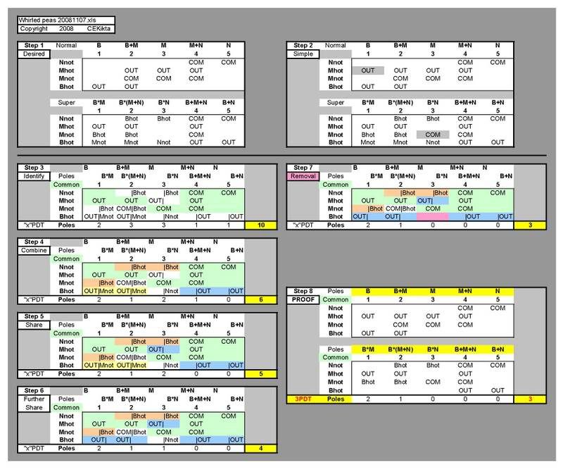 Oh woe and misery, I also can only find use for a 3PDT switch, but I believe that I realize your desired combinations in the desired order. Now, it's late and I've had a full day so I may still be lost in musing on interbrane quantum phasing, but I'll revisit this on the morrow since it makes way too much sense now. This is the path I would (and do) follow for most all designs. /pathNow, you may have done exactly this, but I don't "see" it. Done is.  No. The original Mike Richardson design is the second one of his that I posted. It did B+N and B*N in the middle position. This is the one that I drew for my design. The first Mike Richardson design that I posted (the modded mod) is the second one that he did adding M and B*(N+M) in place of B+N and B*N. |
|
|
|
Post by ChrisK on Nov 6, 2008 18:33:45 GMT -5
They were great at moving cash out of yer wallet.
|
|
|
|
Post by ChrisK on Nov 6, 2008 16:29:40 GMT -5
..or a power chord.  |
|
|
|
Post by ChrisK on Nov 6, 2008 13:51:23 GMT -5
Oh, come on, give quackery a chance.... Oh, uh, does this mean that you do get some mice some more? I live in such an area. We generally use a liberal ( ;D ;D ;D) application of jacketed lead projectiles at around 1,200 to 3,300 fps. This seems to work well on any critter not wearing kevlar.  |
|
|
|
Post by ChrisK on Nov 6, 2008 13:33:29 GMT -5
tedfixxI presume that you meant; NORMAL: B, B+M, M, M+N, N SUPER: B*M, B*(M+N), B*N, B+M+N, M*N Your desired combinations are nearly identical to a Mike Richardson design of yesteryear. It does the following: NORMAL: B, B+M, M, M+N, N SUPER: B+M+N, B*M, B*(M+N), M*N, B*M*N It might be fairly simple to modify the B*M*N into a B*N, you'll have to look at it. I don't want to disappoint you, but it only requires a 4P5T super switch and a 2PDT.  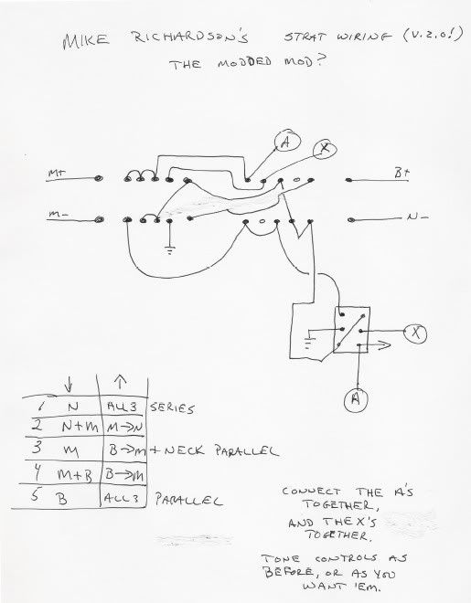 This was his original version, 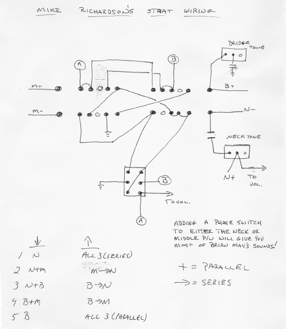 and my implementation of it, Mike Richardson wiring with phasein here. The Padouk Caster
|
|
|
|
Post by ChrisK on Nov 5, 2008 19:11:48 GMT -5
My approach is to measure every component before I solder it in.
Ya never know......
The other thing to be aware of are anti-static precautions..
|
|
|
|
Post by ChrisK on Nov 5, 2008 12:41:53 GMT -5
One of the things that can be done to determine two of the leads on a transistor is to measure the diode drop using a multi-meter that has a diode detector (this is usually a position on the selector switch with a diode symbol).
Most silicon diodes will have a drop of about 0.65 VDC and most germanium diodes will have a drop of about 0.35 VDC. The operative word is "about".
You need to know the voltage polarity coming out of your meter when using this function. Use another meter set to 20 VDC (if your meter has a 9 VDC battery) and connect it to your meter while it is set for diode detect.
Measure the polarity of the emitted voltage. Keep track of which test lead is positive.
Once you know this, you can detect diodes such as the base to emitter junction inherent in every bipolar transistor by measuring from lead to lead to lead both ways (this is 6 tests).
Now, you know for relative certain that the third lead (the one that doesn't belong to a diode) is the collector. You also know that the other two comprise the base to emitter junction.
If it's an NPN, the base will be the lead connected to the positive voltage lead from your meter and the emitter will be the lead connected to the negative voltage lead from your meter.
If it's an PNP, the base will be the lead connected to the negative voltage lead from your meter and the emitter will be the lead connected to the positive voltage lead from your meter.
This doesn't tell you everything, however;
if you know the base material polarity (NPN/PNP) it tells you the pinout, and
if you know the pinout (CBE) it tells you the base material polarity.
|
|
|
|
Post by ChrisK on Nov 5, 2008 12:26:12 GMT -5
D2o is correct. The only definitive thing that the resistance of a pickup coil tells you is the resistance of that pickup coil.
While pickups with higher coil resistances "generally" have more turns of wire, all wire is not the same gauge, and the individual gauges of wire from spool to spool (and within a spool) vary.
Subtle variations in the tension applied to the wire while winding also makes a variation in the resistance.
The best place to find info on the resistance of a particular maker's products is on their web site.
|
|
|
|
Post by ChrisK on Nov 4, 2008 15:12:58 GMT -5
Search me.  (Well, go search the web.) |
|
|
|
Post by ChrisK on Nov 4, 2008 15:00:34 GMT -5
Electricity doesn't have a backwards or forwards for flow direction, it just flows in all possible paths at once, limited within a given path by the impedance of said path.
An RCI detects unbalanced current flow between two conductors which comprise a single circuit loop. The unbalance indicates current leakage outside of the loop, and hence a safety fault.
Part of the difficulty in applying this to guitar amps is that the loop circuit from the guitar is minuscule and inherently unbalanced due to it being a conductor surrounded by a shield. Unbalanced current flow is not necessary a fault condition.
What is a fault condition is current sourcing out of the amplifier input back to the guitar. U.L. Listing for a product in the U.S. generally addresses safety and the effect of a single component failure causing a hazard. Unfortunately, safety standards evolve and the early standards applied to guitar amplifiers were not as comprehensive as those today.
Furthermore, many amplifiers were built by hand using materials that did not have the long-term life necessary for decades of use. Few products are produced today using rubber insulated wiring, for instance.
Also, the grounding practices (or lack thereof) of the past amplifier designs leave EVERYTHING to be desired. In the U.S. we have a three wire outlet. One is a SAFETY ground. Unfortunately, there are still many things supplied with a two wire mains cord.
Many of the instances of electrical shock from amplifiers do not come from the amplifier itself, but from the defective house and building wiring.
There are outlet testers available that determine any fault conditions and indicate them with LEDs such that anyone can determine the safety of said outlet.
You all DO use these BEFORE EVERY instance of plugging in an amplifier, whether at a performance or in your house, don't you?
The use of an RCI/GFI on every electrical outlet that might lead to an electrical shock is mandatory. Even if it's not mandated by code, it should be driven by avoidance of operator stupidity.
A young aspiring guitarist was being shocked when he played barefoot thru an old amp on a concrete floor. His uncle said "wear your shoes". I said "fix the damn outlet".
So, an RCI/GFI belongs on/in every outlet used for musical gear.
While we could design such protection for an amp, any such protection would depend on the outlet for its proper operation anyway.
The safety cap supplies a modicum of protection against erroneous AC current coming out of the amp input (capacitors pass AC as a function of their and circuit impedances), but block steady-state DC (transients still pass since they are comprised of step-functions).
The better way to practice safety cap use is to use two of them, in an insulated enclosure, at the input to the amp, capacitively coupling both the signal and shield to the guitar. Its still a band-aid.
There is that other solution that has excellent fidelity, minimal tone-suck, ease of operation, profound resistance to any electrical potential short of lightening, and has been available for years.
RF
|
|
|
|
Post by ChrisK on Nov 3, 2008 19:20:17 GMT -5
|
|
|
|
Post by ChrisK on Nov 3, 2008 19:11:12 GMT -5
I looked at the Gib$on Melody Maker RI a couple of years back when they first appeared. The body was about 1 1/4" thick and I wasn't impressed with them. Of course, I'm not impressed with most Gib$ons, as I feel that they cost about twice what they should. The only actual Gibsons that I have are a faded SG (I tried about 20 of them before I found one with the tone and feel that I wanted - it ended up being one with a four-piece body), and an ES-137 that has great tone and cost me $1,300 new two years back. Ok, maybe they're only overpriced by 50%. The U.S. dollar has gotten stronger lately so importing might work out. www.x-rates.com/(BTW, I saw gas last week for $2.169 per gallon just south of Cleveland, Ohio.) Or 36p per litre. Where I live in west PA it's for sale for the ungodly price of $2.599 per gallon. What energy crisis?  |
|
|
|
Post by ChrisK on Nov 3, 2008 17:54:50 GMT -5
That's because, in my experience, I haven't found a supplier that actually KNEW the schematic representation of their switches.....(or what the words meant).
|
|
|
|
Post by ChrisK on Nov 3, 2008 17:52:02 GMT -5
While one can put a second 500K resistor in parallel with a 500K one to convert the result to 250K, one cannot just place a 500K resistor across a 500K pot to realize a 250K pot in all of its response characteristics. A pot has three terminals. A 500K pot with the same ratio-metric taper as a 250K pot has a different taper effect when loaded by a 500K fixed resistor and the same external circuit (tone control, cable, amp input). A 250K volume pot, when set to half of its resistive value, has an effective output resistance of 62.5K. A 500K volume pot, when set to half of its resistive value has an effective output resistance of 125K. (These are both Thevenin equivalencies - DC circuits 101). The addition of just an external resistor will change the loading presented by the pot when it is full-on to the desired pot value, but not duplicate the rotational response of the desired pot value. It may be close enough, or it may be dissatisfactory, but it won't be the same. The only way to exactly reduce a 500K pot to 250K is to use a dual element 500K pot and wire each of the three terminals to its neighbors like terminals. If it was easy to do with just a resistor, we'd have only 1 Meg pots that came with two resistors. |
|
|
|
Post by ChrisK on Nov 3, 2008 17:31:28 GMT -5
Why do you want a dual/concentric linear taper pot?
|
|