|
|
Post by ms on May 7, 2021 14:14:05 GMT -5
The short answer is because the aperture is determined by the poles, and they are narrower than the coil. So when the poles magnetize the string, the part of the string over the poles contributes the most vibrating field pointed down through the coil. This falls off quickly as you move along the string away from the poles. Also, because the pole has permeability, it amplifies the field from the part of the string right above it. Flux passing through the coil, but away from the poles, does not get so amplified. I understand how the pole piece can be a dominant effect over the area of the loops alone, but what if you had a standard pole piece, but the coil was six inches in diameter. Wouldn't the sum area of flux change be so wide that is wouldn't see non-cancelling flux change of string segments that are much less than six inches? If the pole piece is still dominant even with a very wide loop, then maybe suppose the pole piece is a ceramic magnet and contributes now permeability. Supposing this is the case, the extra width of a P-90 or a Microcoil would be trivial, but it's the principle of the thing. Yes, if you make the coil too wide you get cancellation, but I think the aperture is still bounded by the pole. You could figure out which part of the aperture gets canceled first as the coil width increases, but is this really of much practical importance? |
|
|
|
Post by ms on May 7, 2021 7:25:08 GMT -5
The aperture is not determined by the width of the coil. I do not see why you are thinking this, but it cannot be true. I know this has been discussed before, but I'm still not sure why this would be. The harmonics are suppressed when you have a receptive field that is so wide that it experiences both positive and negative flux change in tandem, and the two cancel out. The objective then is to have an inductive field that is narrow enough to capture a positive movement would also seeing a corresponding negative movement. How would the wider loops of a wider coil not result in the capture of both positive and negative flux changes of higher harmonics, more so than smaller loops? The short answer is because the aperture is determined by the poles, and they are narrower than the coil. So when the poles magnetize the string, the part of the string over the poles contributes the most vibrating field pointed down through the coil. This falls off quickly as you move along the string away from the poles. Also, because the pole has permeability, it amplifies the field from the part of the string right above it. Flux passing through the coil, but away from the poles, does not get so amplified. |
|
|
|
Post by ms on May 6, 2021 17:36:49 GMT -5
The coil doesn't generate harmonics. It is the non-linear relationship between the position of the string and the amount of flux that it puts through the coil that generates the harmonics. From common experience, the sensitivity of the pickup falls off rapidly as the distance of the string from the pole increases. But this happens over distances that are comparable with the distance the string moves through as it vibrates. There you have the non-linearity. The gain changes during the string movement. Put in a sinusoidal string movement and out comes a voltage which includes harmonics.
That's interesting, but how does it relate to the aperture window of a pickup? Magnetic power decreases by the inverse square law, so whatever magnetism in a string has that much less influence the farther away from the coil, and I already explained that flux lines traveling along the string contribute virtually nothing to the output. I may be misunderstanding something, but it appears you are conflating two unrelated functions. A magnetic dipole has a one over distance cubed function, not squared. (There are no magnetic monopoles.) A collection of dipoles could fall off slowly nearby and then like a dipole far away. |
|
|
|
Post by ms on May 6, 2021 7:14:01 GMT -5
"It’s not the same as flux lines coming in from the side of the string." What matters is the magnetization excited in the string; the string is what moves and causes changing flux through the coil. Of course the result of the flux lines from the magnet producing magnetization in the string when located on the side is not exactly the same as underneath, but it apparently is very close. The magnetization excited in one location of the string affects that in neighboring locations. The result is a "self-consistent" solution in which the geometry of the high permeability material plays a huge role. For example, wind some closely spaced turns around a high permeability toroid, covering only a small part of the toroid. The flux is almost totally confined to the toroid and uniform around it. This looks nothing like the field produced by the coil with no toroid present. |
|
|
|
Post by ms on May 5, 2021 6:59:55 GMT -5
This app should clear up how the magnetic and/or coil aperture width, as well as the pos along the string, etc affects harmonics, but it doesn't address the affects of proximity and coil density: www.till.com/articles/PickupResponseDemo/index.htmlHere's what makes sense to me about string proximity and aperture. The flux lines come out the top of the pole in a funnel shape. The flux lines around the edges of the field hit the string more straight on when that pole is closer to the strings. Those same lines would then hit the string at more of an angle when the pole is further from the string, therby contributing less to the total pickup output. The total magnetic aperture power might then acually become slightly thinner, but I doubt it makes much differnce in magnetic aperture either way. Raising a pole screw within a magnetic insert may have some audible affect on aperture with regard to the total length of the pole, but I think the effect on note timbre is less sigificant than changing the coil height itself has. I only wish BL was here to clear this up, but I know someone who would have opinion on this over at Wilde-gate.  Tillman assumes the aperture is the pickup width. He has hedged on that a bit in the last few years. Assuming something does not clear up anything. The string is a high permeability very elongated object, and so the string magnetization is along its length. The direction must switch over the pole. This means that the necessary field from the string magnetization pointing along the axis of the coil is almost entirely over or very near the pole. You cannot get much signal from anywhere else on the string. aquin43 showed that the magnetization pattern of the string has a high degree of symmetry in the direction around the string. He showed that the magnet can be removed from below the string and moved 90 degrees so that the field comes in from the side without changing the output of the pickup significantly. |
|
|
|
Post by ms on May 4, 2021 10:50:08 GMT -5
Can't it be like speaker driver measurement ? Using semi-inductance model of 5 parameters instead of one to get way better simulation results. Even not understanding the science behind, i used it to measure with a artabox with Arta/Limp a 12" subwoofer so that hornresp (modern speaker sim tool) result agree with real life mic measurement. Few (very few) speaker makers gives those parameters on demand, but they measure it in factory, it take few seconds. Those parameters are the only useful when speakers deals with eddy current (mostly subwoofers due to their long voicecoil), but are still interesting for extented bandwith drivers. Shorting rings inside speaker motor allow to reduce a lot intermodulation distortion, and the effect is easy to see directly on impedance curve when used to look at. So that same "inductance" with different semi-inductance parameters (and so different impedance curve) can lead to noticable distortion level/shape/response. Is there something in this direction in pickup modelling knowledge ? Yes, a semi inductor can be modelled as a series of inductors each shunted by a resistor. Zollner illustrates how this arrangement can be used to model a pickup inductance, and hence its impedance, and a similar arrangement with one shunted section (sometimes replaced by a lossy coupled inductor) and one pure section was referred to in the thread "a new model". The data for such a model can only be obtained by measuring the impedance at the pickup terminals, not the response to a magnetic exciter. Then, there remains the shielding effect of the cover and other parts which comes between the string and the coil but doesn't necessarily appear in the impedance. In some pickups this can be an important part of the response.
So a full model can rapidly become very complex and, while it is useful in simulations, it doesn't lend itself to intuitive appreciation of the pickup's possible sound.
I think that modeling an imperfect inductor across a broad frequency range can be important in design work. But not so much for specifying what influences the sound. The impedance of a pickup is low compared to the load at low frequencies. Therefore, unless you work to make it not true, the response of a pickup is flat at low frequencies (once you have allowed for the standard 6db/octave increase). This extends somewhere up into the lower midrange, but the interesting part starts as you approach the resonance, and then above the resonance it all goes away. But there are interesting questions. For example, if a pickup has a lot of eddy currents, can the inductance change enough over the frequency range of the peak to be important? That is, given that the location and width of the peak are important, could the details of the shape, as determined by the change of inductance with frequency, also matter? That might sound like a silly question, but the ear/brain is a really sensitive analyzer in that frequency range. |
|
|
|
Post by ms on May 4, 2021 7:04:44 GMT -5
Specs can also be used to baffle brains... you mentioned something there that reminded me of that right away - I've seen the resonant peak given as a specification. By itself, unloaded resonant peak frequency is a relatively unimportant spec because of the fact that it is mainly influenced by inductance and capacitance, inductance is not altered by the guitar circuit very much but capacitance definitely is. But the capacitance is always significantly overshadowed by the guitar circuit capacitance. Hence inductance by itself, although it is a much simpler data point, is a far more revealing aspect that tells you far more about how it will operate in situ than resonant frequency ever will. But it sounds really knowledgeable and technical so someone can pretend to be giving out specs when in fact almost nothing useful can be learned from it.
If there is ever a useful "lingua franca" that everyone could use to characterize pickups technically, besides the general construction and type, it would be inductance, loaded resonant frequency and loaded Q. A standard load doesn't exist in the industry, around here we kind of settled on 200k/470pF because it's pretty close to most guitar circuits. That would be a problem in an industry that has no governing body or professional association to organize standards (such as IEEE). It's the 2 dimensional map produced by loaded resonant frequency and Q that mainly defines pickup tone differences. Most other specifications and details are inputs into those characteristics. Thus there are often many ways to target the same data point in that space.
But it would be a huge step, really the first step, if manufacturers would begin listing the inductance and preferably also the frequency at which that is measured (ideally 100/120 Hz, whichever doesn't pick up line noise 50/60 Hz in their country).
Ken man, truer words never spoken ;-) (being "this way inclined" i assure you, i've lost more sales in the day job then i've made from being "overly technical" - so i know exactly where your coming from with it sentiment) I agree entirely on the inductance aspect too - obviously, its an unrealistic expectation for Joe public, but purely from experience with enough pickups, i wager most of us at this end of things, can tell exactly what a pickup is going to be capable of based purely on its inductance and general construction (you know? In very broad strokes) - but, as this threads started to show - even we cant agree on a standard for testing that! (I've always been a 1kHz man myself  )
It does beg the question though - is this not a case of "which test frequency is best?" but, rather, a case of "can we all just agree on a frequency to test at?" (and 1kHz is likely the simplest, because its the setting most LCR meters are capable of) - if you do get 2 pickups that do, by some miracle, show the same inductance at 1kHz, then so be it - a bode plot will most likely show a difference within the resonance/Q factor right? I mean, i'm as green as they come to bode plots as a tool for testing, so maybe i'm way off the mark, but that'd be my thinking on it?
I'm actually see stuff in my very preliminary testing that doesn't quite add up to (magnetic spacers on humbuckers are odd - i can see variation on a parametric EQ, you can actually hear a difference on recording (which indicates its a big enough difference to matter!), but that doesn't translate into a change in capacitance, inductance, shift in peak or Q. (although, I'll concede that my testing isn't 100% perfect currently - definitely at the C- stage - must try harder! haha)
Testing and specifying are two different things. An engineer tests a pickup to understand it. You want to test over a brand frequency range in order to understand all the details. But when you make a specification, you want as few numbers as possible, and that means they must emphasize what is most important in determining the sound of the pickup. 3KHz is where the ear-brain works really well. A measurement of inductance at 3KHz includes the effects of eddy currents and so is a better predictor of the resonance frequency than a lower frequency specification. The Q at 3 KHz includes losses resulting from eddy currents and so is a better predictor of the width of the resonance than a lower frequency specification. |
|
|
|
Post by ms on May 3, 2021 9:34:40 GMT -5
That's why it's confusing. A pickup could have a loaded peak at 2kHz, another at 4Khz, and at 3kHz both measure the same despite sounding totally different. Those pickups have different values of inductance; they do not measure the same. They might have the same Q, but it is the difference in inductance that counts for the location of the peak. |
|
|
|
Post by ms on May 2, 2021 18:05:40 GMT -5
If there is ever a useful "lingua franca" that everyone could use to characterize pickups technically, besides the general construction and type, it would be inductance, loaded resonant frequency and loaded Q.
I think that can be expressed as two numbers associated with the inductor: its value and its Q. They should be specified at a compromise frequency in the range where loaded resonances are located, say 3KHz. |
|
|
|
Post by ms on May 1, 2021 12:01:05 GMT -5
No, man. It's a proximity-based thing. The lower to upper harmonic strength increases when any pickup is raised closer to the strings because the stronger vibrations become more emphasized compared to the weaker ones, same as with a microphone. It is indeed the same basic function. Microcoils have the same aperture as Fender SC's. The magnetic aperture does spread a pickup is lowered, but it also weakens exponentially around the edges as the flux lines become more horizontal, so it's really just the coil width that determines the aperture window, unless there are also vertically aligned magnets outside the coil or something that increase power in the edges of the coil. Aperture induced harmonic cancelations start at a specific range for each string and follow corresponding octaves i.e if it starts in the 4kHz range on one string with a given aperture, it would start in the 1kHz range at 2x the aperture. There is some increase in lower to upper harmonic strength for wider apertures, but it's much less significant than the cancelations. I'll read back over that section and get back on this. The aperture is not determined by the width of the coil. I do not see why you are thinking this, but it cannot be true. |
|
|
|
Post by ms on May 1, 2021 11:41:01 GMT -5
(I can not get the images to post in the right order, but they are labeled air for air, stl for steel and cer for ceramic.) The question remaining from that video is this: why does the ceramic magnet cause the inductance of the pickup to drop relative to no magnet? We can find a plausible answer, but not prove it behind any doubt. First it is important to understand the characteristics of ceramic magnets. We look here: en.wikipedia.org/wiki/Ferrite_(magnet). Under "Hard Ferrites" (meaning permanent magnets) we see these two characteristics: 1. Ceramic magnets are "very permanent", that is, it takes a very high field to affect their magnetization or cause demagnetization. 2. They have high permeability. Well, surely both of these things cannot be true, and so we need to run a test. The only ceramic magnet I have is from a mini humbucker, and since I can measure the impedance of a pickup very accurately, I take one of the mini hb coils and measure the impedance with three "cores": air, steel, and the ceramic magnet. The ceramic magnet is not intended to be used as a core for the coil, but it fits, so why not. Air and steel are for mental calibration, and then we want to see where the ceramic magnet fits in that scheme. So the first two attachments show information derived from the impedances of air and steel. To get this information, the high frequency part of the impedance is used to derive the pickup capacitance by a fitting technique, and then the impedance of this capacitance is "unparlelled" from the while impedance. This is better thought of as subtracting the admittance of the C from the whole admittance, and then converting back to impedance. So the imaginary part of this impedance, call it Zu, is the inductive reactance. It might not increase linearly with frequency because of the effect of eddy currents. Air does not cause eddy currents, and the magenta line, Zu.imag, on the plot for air follows the dashed line (the inductive reactance of Lcoil, the inductance at very low frequencies extended to high frequencies as if it was the true inductance).  On the other hand, steel is both permeable and conductive. Lcoil has more than doubled from that of the air core, and the magenta line deviates downward from the dashed line.  So what is ceramic like? The plot shows that it is within about 1% of air. So it provides the high microscopic currents to make a strong magnetic field, but otherwise it almost might as well be air.  So how can it reduce the inductance of the pickup? It is really very simple, I think. With my Tesla meter I measure the field made by the ceramic magnet and some AlNiCo magnets. (They were actually for a regular humbucker, and so a bit larger, but never mind.) The ceramic is about twice as strong as the strongest AlNiCo. So I think what is happening is that the ceramic magnet moves the steel in the humbucker poles a bit further along the hysteresis curve to where the permeability starts to drop, that is, in the direction of saturation, but not nearly there. |
|
|
|
Post by ms on Apr 29, 2021 15:49:20 GMT -5
Great, so I had that backwards too  but that does make more sense now that I think about it more: The eddy currents oppose the change in the magnetic field arond the coils, and weakened field -> lower inductance. I guess I was just trying to make sense of the steel ruler increasing the inductance, but your comment of there just being more steel around the coils (in addition to the pole pieces) would explain it. I also got the sense that the guy in the video doesn't really have a solid grasp of the subject, but couldn't put my finger on it. But it did seem very strange to me that he was talking about the materials of the magnets and their "iron content", which would lead me to believe the effects of the steel ruler and ceramic wouldn't be so different. The result seemed contradictory to me, given what he was talking about. Although I believe AlNiCo contains at least some iron as well? Also, thanks for mentioning saturation and hysteresis curves, i think I'm understanding it better now. A key thing to remember is permanent magnets tend to have low permeability. It sort of goes along with many magnetic domains already lined up and not so easy to change. For example, vacuum has a (relative) permeability of 1. Neodymium magnets, very strong, are 1.05. AlNiCo is typically a few times a vacuum. AlNiCo is high enough so that the effects of putting steel (100+) in contact is not such a simple problem to solve sometimes. This why modeling programs have become so popular. My intuition on these sorts of problems is very approximate, and so I think a bit of computing is a really good thing. AlNiCo materials here: en.wikipedia.org/wiki/AlnicoSimple test to show an effect of magnetic field strength on inductance: Wind a Fender type signal coil pickup using non magnetized pole pieces. Measure the inductance. Magnetize the poles. Measure again. |
|
|
|
Post by ms on Apr 29, 2021 14:53:36 GMT -5
Thanks, That does clear it up quite a bit. So apparently the source of my confusion was that I ignored the pole pieces, and it's the pole pieces that are in an external magnetic field of the pickup magnet. It's been more than a decade since I studied this stuff at uni, and of course we didn't specifically look at guitar pickups. So I was thinking more about the more usual case of current in the coil inducing the magnetic field and how materials around the coil respond to it, obviously the field of the pickup magnet is much stronger. But am I right in thinking that it's the currents induced in the non-magnetized steel ruler which increase the inductance in that case? Also, if you or anyone else can provide more insight as to the results in the video, I'd be interested to learn more. Eddy currents reduce the inductance, not increase it. But if you make the measurement at 120 Hz, the frequency is too low for there to be significant eddy current effects in a pickup. The ruler just adds more steel to the system; exactly how this increases the inductance is a complicated question. I would model a 2D approximation in FEMM to find out. Maybe that guy really does believe what he is saying, but notice that when he told you that the strength of a magnet does not influence the inductance, and to prove that you demagnetize a magnet and then put it back in the pickup, he did not actually do that test. For example, a very strong magnet saturates the cores, or at least gets to a flatter part of the curve, reducing their permeability maybe to just about one, and thus decreases the inductance relative to a weaker magnet. It is all in the set of hysteresis curves. Certainly the strength of the field does influence the inductance, and by not understanding what he is doing and selecting results carefully, he can get results that reinforce his lack of understanding. This is, after all, a complicated subject. |
|
|
|
Post by ms on Apr 29, 2021 13:29:57 GMT -5
I am not sure how deeply you want to go into this, so I will give a short, general answer. The magnet does not alter the inductance because of its permeability. The permeabilities of the magnets are low compared to that of the steel in the cores; how could they have any such direct effect? Instead, the inductance is modified because magnetizing the steel alters its permeability, and this can be up or down depending upon the degree of magnetization.
|
|
|
|
Post by ms on Apr 28, 2021 18:34:01 GMT -5
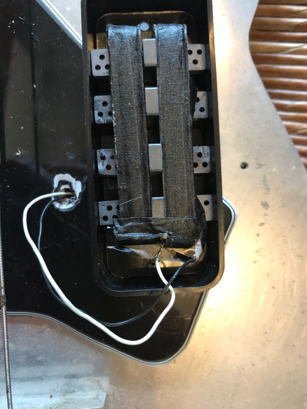
So we have the unused coil (uuc) and used coil (uc). How does the uuc cause the changes in the frequency response of the uc? I see two possibilities, damping of the response of the uc from coupling to the uuc, and signal transfer from the uuc to the uc from the coupling. Let's define the meaning of these two possibilities by showing how to measure the effects. Use a tiny exciter coil that fits on top of a pole piece. This allows exciting one coil with almost nothing picked up in the other coil. So to measure damping we excite the uc and make measurements with the uuc open and shorted. (The uc has the usual 500pf cap to move the resonance down to something useful.) Significant damping would be indicated by appropriate differences between the measurements in the two cases. For the signal transfer case, we move the exciter coil over the the uuc, but continue to look at the output of the uc. With the uuc shorted, but excited, some current will flow in the uuc that will induce voltage in the uc. We look for a response, which, when added to the normal response of the uc, could cause the appropriate spectral changes. So the first two images are the damping test, uuc open and shorted. There is no significant difference, and so there does not seem to be any damping.   The next image shows the signal transfer from coupling. This looks like what we need.  |
|
|
|
Post by ms on Apr 2, 2021 13:04:51 GMT -5
Isn't there a risk that the potted inductor's permeability will interfere with the measurement? Generally, there could be, since inductors are constructed with different core materials. But this type uses a ferrite core, which has an exceedingly high permeability and so is effectively transparent as far as the measurement is concerned. I also A/B tested it with a full sized air-core test coil using the same pickup. The alignment of results was almost perfect, I can't find the plots right now because of all the PC swapping around I had to do recently. As I recall, as near perfect as two consecutive plots using the same test coil. The image shows that a very small ferrite core exciter coil has a small effect on the pickup impedance. The top left shows the test pickup and the driver coil. When placed on a pole piece, the coil becomes magnetized, and thus tends to stay in place. The coil has three turns and is apparently under 1 micro Henry in inductance. It is driven from the headphone jack of an element 24. I integrate for a minute or so to get adequate signal to noise ratio. A response measurement is shown to the right. The test wave form is a pair of complementary codes, together containing all relevant frequencies nearly uniformly. The processing uses a cross spectral technique and the output is a ratio in which any frequency variations in the spectrum of the test waveform are removed. The instrument input of the element 24 has a high enough capacitance to lower the inherent resonant frequency a lot. I did not use a low capacitance buffer for this measurement. The lower two plots show the pickup impedance without and with the driver coil in place. There is a small effect on the inductance and resonant frequency. The frequency measurement is very accurate since there is no significant loading effect. I think that a larger piece of ferrite would have a larger effect on the pickup. 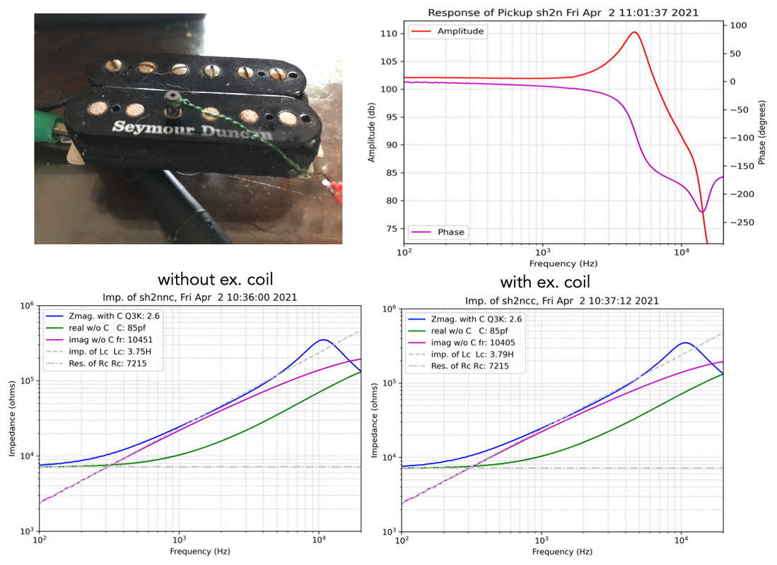 |
|
|
|
Post by ms on Mar 17, 2021 11:15:28 GMT -5
|
|
|
|
Post by ms on Mar 10, 2021 21:17:01 GMT -5
It appears that as the exciter coil is moved with respect to the slot, the Q of the resulting resonance varies. In a low Q system the frequency of the peak of the response changes as the Q varies, even if the defined resonant frequency, the boundary between inductive and capacitive, does not..
|
|
|
|
Post by ms on Mar 9, 2021 5:46:44 GMT -5
I have some designs on the Marshall forum for reactive attenuators where an air-core inductor is used to give it a varrying impedance to match that of a speaker. If you want to match the impedance of the speaker perfectly, you need some eddy current loss in your coil since the speaker coil has some such loss. The amount presumably depends on magnet material, etc. Probably not a big deal, but maybe there is no need to try to eliminate the accidental eddy currents. |
|
|
|
Post by ms on Feb 25, 2021 6:35:58 GMT -5
I think there is a limit to the localization. The current change due to the capacitance between turns a and b induces some voltages in all other turns because they are all magnetically coupled. It might be interesting to model a simple case, starting with low mutual inductance and increasing it until an effect is seen.
A single layer rf coil can be treated as a transmission line. The inductance and capacitance per unit distance determine the impedance. Its length is short compared to a quarter wavelength, and so it is capacitive, with the value computed from a very simple equation. I have read that this method works very well in many cases. I think that this works because the magnetic coupling is largest between turns that are close together, making this simple model possible.
But it does not work for a guitar pickup, a multi-layer coil with a huge number of turns. Perhaps a different approximation is possible taking advantage of a limit involving the large number of turns and the fact all the voltages resulting from magnetic coupling between turns appear in series.
|
|
|
|
Post by ms on Feb 24, 2021 12:28:01 GMT -5
I do not think that it is a anti-science to recognize what sets the overall frequency response of the system and not mess with it. Add a preamp and you can have whatever frequency response you want. This includes especially more high frequencies, almost certainly not what you want. Add a preamp and you have to include a way to keep the sound the way it was before you added it as one possibility.
Limitations in the system establish an essential part of its character, which of course you can achieve by other more complicated means if you want.
|
|
|
|
Post by ms on Feb 7, 2021 10:00:40 GMT -5
aq's model uses delay line elements to simulate the movement of a pulse on the string. The assignment here appears to approximate a delay line from each direction from the picking location using Ls and Cs; that is a kind of transmission line. You want the speed of propagation to match that of a guitar string. The L and C per unit distance determine that. So you have a little bit of playing around and simple calculation to do to get something that works.
|
|
|
|
Post by ms on Feb 3, 2021 14:22:34 GMT -5
Looks like a great meter. I like the way the display is set up. I have not located a source that will ship it to Puerto Rico, but that might happen in the future.
(Watch out for the 1832C, which does not have the higher frequencies.)
|
|
|
|
Post by ms on Dec 23, 2020 19:15:55 GMT -5
So basically, for a noob like me: Impedance is somewhat equal to the resistance at low frequencies (from what I could gather by reading up a bit). But, then the impedance increases at higher frequencies. Is there any rule of thumb on how much it increases? Does the impedance of a series humbucker increase more or less compared to the same pickup wired in parallel? Yes, the impedance of a pickup is just the winding resistance at very low frequencies. It is a resistor in series with an inductance, and the impedance of the inductor starts to matter as you go higher than the lowest guitar frequencies. The impedance of the inductor is the inductance value times the frequency times two times pi (3.14...). But the impedance of the resistor and the inductor are different kinds of quantities, and so you cannot just add them to get the total magnitude of the impedance. You have to square them, add these squares, and then take the square root. (Yes it is more complicated than we would like.) At higher frequencies, the capacitance matters, too. Antigua has a lot of plots of the frequency responses of various pickups on this site. This is controlled by these impedances. |
|
|
|
Post by ms on Dec 23, 2020 9:52:11 GMT -5
Thanks for your detailed response! Now it becomes clearer to me why the pickup in parallel tends to overpower the one in series in a dual humbucker guitar. The solution could be to run both in parallel and then filter out some of the highs (for me at least). A question though: Is the impedance of a pickup directly tied to the resistance, or are they completely independent? I noticed your estimated impedance values also match the expected resistance from a vintage tele or a dual PAF guitar. I do find it fascinating that a humbucker by itself loses output when wired in parallel, but gains perceived relative output when combined in parallel with a series humbucker. Impedance is the combination of DC and AC resistance, also stated as "resistance" and "reactance", also stated as "real" and "imaginary" resistance. DC resistance is what is obvious, the spec listed for every pickup, and then you add to that the "resistance" that comes from the inductance of the coil when the electrical signal is alternating, which can be as high as 50k ohms at the resonant peak. Let's look at this from the point of view of a meter, Extech or other. If you set it up to measure inductance, you get two numbers. One of them can be expressed as Q, D (dissipation) or R. The last is what some people mean by "ac resistance": it is related to power dissipation, but at the frequency of measurement, rather than at dc. The other number is the inductance, which is an impedance at the measurement frequency, but since the current is 90 degrees out of phase with the voltage, there is no dissipation of power, and it is better not to refer to it as a resistance, but as a reactance. For a pickup at resonance, the effect of the inductance and capacitance cancel, and the resulting high value of ac resistance can be as much as several hundred thousand ohms. But you might not measure such a high number unless you use a technique that removes (nearly) all the loading effect of the measuring instrument. |
|
|
|
Post by ms on Nov 17, 2020 5:54:37 GMT -5
All good points, thanks ! That being said if you compare the measurements to say the chopper here: guitarnuts2.proboards.com/thread/8502/dimarzio-chopper-analysis-reviewthan you can see the loaded alumitone still has a higher cutoff. I've used the chopper and it didn't have this issue at all. Admittedly the alumitone test was for a single coil version, it's possible the humbucker size measures differently but I doubt it would be drastic enough to explain the problem. Then this is a mystery! I would check the magnetic field along its length with a meter. Also measure the output from a tiny driver coil along the pickup (which should be the same even if the magnet varies). Somehow, I do not expect that this will be easy to find. |
|
|
|
Post by ms on Nov 16, 2020 6:13:39 GMT -5
Thanks for the reply ! I agree his writing is nonsense, though in practice the resistance is still lower than most other pickups including filtertrons. Good point regarding the filtering, the pickups indeed could do with more highs, but the high E is still far below the cutoff frequency of the pickups. It seems to be more an issue with the relative mass of the string compared to the others. Edit: either that or the magnetic field doesn't extend far enough but that would seem weird given that the magnet extends past the string by at least 1.5mm Perceived volume is to some extent a function of harmonic content. Have you measured relative string volumes (with careful picking), and compared to measurements made with your previous pickup? Harmonics that are low in actual power can have a significant impact on the perceived level because the ear-brain combination is very sensitive in the 2-3 KHz, or so, range. Pickup resistance is an easy measurement, but difficult to interpret. For example, a typical humbucker has high enough eddy current losses to make a significant difference in the tone near the resonance, which has a big impact on the sound. In the Lace AT you have some eddy losses, presumably, and the transformed up effect of the "coil" resistance. It would take careful measurements to separate out these effects. Edit: Antigua did his standard measurements and one conclusion was that when loaded as typical, they do not have much of a resonance peak, and thus they have quite a bit of loss. It seems to me that the loss is much higher than you would expect from the dc resistance alone. guitarnuts2.proboards.com/thread/7821/lace-alumitone-analysis-review |
|
|
|
Post by ms on Nov 15, 2020 11:40:52 GMT -5
Is it really the string volume that is less, or is it just lack of high frequencies, which affects the highest string the most? Lace avoids the issue of the spectrum of the pickup by saying that it has more bass and more mids, which is a way of saying that it has relatively less highs.
You need to look at anything Lace writes with caution. This is his basic "sell":
"This radical departure from pickup design is aluminum based, rather than copper. Result: less resistance, higher output coupled to a "current driven design" as opposed to conventional voltage based pickups.
The aluminum water jet cut exoskeleton is then matted to a micro winding using 90% less fine copper wire, a low impedance/high impedance pickup is then created."
Pure nonsense, right? Aluminum has a higher resistivity than copper. If he made that single turn coil out of copper, the pickup would have less AC resistance, not more. "Current driven design" has no meaning in this context. The coil has a very low output voltage because it has only one turn. The voltage is raised with a transformer to be similar in performance to a regular high impedance pickup. Whatever "voltage based" means, it is just like a conventional pickup in this sense. That is, they all work because of Faraday's law of magnetic induction.
I believe that the resistance he gives is just the resistance of the transformer. You need to add to this (for what counts, the total AC resistance) the resistance of the coil multiplied up by the square of the turns ratio. If the transformer has 5000 turns (it could be more), then the ratio is 25 million. So that very low resistance coil in effect is not so low.
|
|
|
|
Post by ms on Nov 8, 2020 15:50:02 GMT -5
The method I came up with several years ago is:
1. Make the dummy as near to identical to the pickup coil as possible. (This makes it easy.)
2. Make the dummy active. It feeds a FET source follower which can run on low current because it only has to swing the hum voltage, not the signal. (Although it does have to swing the signal current, but that is small for a H Z pickup.)
3. Connect the ground lead of the pickup to the source of the FET (AC coupled) instead of ground. It sees a very low impedance to ground.
So the voltage on the source is the hum voltage from the dummy coil, and it appears in series with the pickup and so it cancels the pickup hum. I forget the details, but it works fine and does not affect the sound from the pickup to a any significant degree. You do need a battery, but life is long since the current can be low. I forget how low.
|
|
|
|
Post by ms on Nov 8, 2020 5:56:31 GMT -5
It makes sense to adjust the relative number of turns for best hum rejection. As for sonic effects, the two coils are connected in series and act as a single inductor in the useful frequency range of an electric guitar.
|
|


 )
)
 but that does make more sense now that I think about it more: The eddy currents oppose the change in the magnetic field arond the coils, and weakened field -> lower inductance. I guess I was just trying to make sense of the steel ruler increasing the inductance, but your comment of there just being more steel around the coils (in addition to the pole pieces) would explain it.