|
|
Post by sumgai on Sept 17, 2019 21:25:32 GMT -5
Dayum, Yogi, that's a nice one! 
While I personally would find it "fiddley" in use (as John would put it), it is fully functional. I think this design is destined for the Modules section, titled something along the lines of "Selectable Blend". Where I'd see this as useful (to me) is the elimination of the pup selector switch - the Swap switch can go between Neck or Bridge, and the Blend pot will give Neck and Bridge, as needed. I don't see twisting a knob quickly as being any different than flicking a switch whilst on stage.
Bonus: the master Vol and Tone pots could both be Fender S1-style switches, giving a stealth appearance to the axe.
sumgai
|
|
|
|
Post by sumgai on Sept 17, 2019 12:07:22 GMT -5
ange,
Sorry to say, but I still see problems...
Consider that blue wire between Neck negative and the Bridge vol pot's terminal that we normally consider 'grounded'. In parallel, if you turn down the Bridge vol pot, you are sending the Neck negative straight to the output (if that switch is closed). Of course, this means no signal at all. (Both leads of the Neck are going directly to the output, and the negative lead is also grounded....) With the switch open, then the Neck will be heard. (But of course, not the Bridge.)
In series we have some different problems, i.e. the Bridge 'hot' now has two paths to follow:
1) If the Bridge vol pot is all the way up, then the Bridge vol pot's entire resistance element is in series with the Neck negative terminal. That'll reduce the Bridge's contribution to the overall sound, by a rather large margin.
2) If the vol pot is turned all the way down, then the Bridge positive is connected directly (via the orange wire) to the Neck negative, but the Bridge tone controls still have that vol pot resistance element between them and the signal.
IOW, when in series your Bridge vol and tone controls won't act as expected.
BTW, when you wish to show separate switches that have a similar function (such as selecting tone caps), you don't need to use dashed lines, or a black box, or some other way of showing their physical function. Instead, you should use labels. For example, switches usually start with a capital "S", such as S1 or S2, like that. Even though we usually see switch labels in Truth Tables, in your case above I don't think that's necessary. A reader who studies it for a few moments will make sense of what your Truth Table says, even without labels. (I feel that including them would just make the table cluttered.)
HTH
sumgai
|
|
|
|
Post by sumgai on Sept 15, 2019 10:14:46 GMT -5
Here are the problems I see with ange's circuit, just above:
1. No pup selector switch - frets want all 4 possibilities, presumably conviently;
2. In parallel or series, each normally grounded vol pot acts as a master, (the standard reason for reverse wiring);
3. In series or parallel, each ungrounded vol pot simply adds a resistance between the pup and output. Often this is not enough to kill the signal, and certainly is unreliable as a blend control of any sort;
4. With only one vol pot ungrounded, the other pot is still a master;
5. In series and with both vol pots ungrounded, the N vol pot will have little effect, but the B vol pot will interact with all of the tone control circuitry, probably in an undesirable fashion.
The fix is simple:
a) Move the s/p switch to just before the output jack; b) Move the ground terminal (and switch) of the N vol pot to the lower lead of the N pup, this will isolate the two pup control circuits from each other when in series.
6) The dotted line between the binary switches indicates that all 4 should move simultaneously, which makes the Truth Table an impossibility.
HTH
sumgai
|
|
|
|
Post by sumgai on Sept 12, 2019 22:50:17 GMT -5
.... Not a fan of this picture. No color key or pickup N S orientation. Errr, not quite, Mark.
Those gray "wires" coming from the pup are actually cable sheathes - they enclose the bundle of individual wires for easier routing through the body of the axe. Once inside, and near to the controls, the sheathing ends, and the individual wires are spread out for connecting as seen fit. And a closer look should reveal red, white, black and green wires to the various terminals.
North/South orientation doesn't matter, that's the beauty of a diagram - it's adaptable to any set of pickups no matter how they're oriented - so long as the pair is oriented in the same direction. (Presumably the two are from the same maker. If not, some experimentation may be in order to achieve that correct orientation.)
HTH
sumgai
|
|
|
|
Post by sumgai on Sept 10, 2019 19:15:08 GMT -5
.... I'm just trying to keep learning As the old saying goes: The day you stop learning is the day you start dying. (Quoted from a source I no longer recall.) |
|
|
|
Post by sumgai on Sept 10, 2019 19:05:06 GMT -5
OK, OK, I give up, enough already.
Have it your way, both of you.
sumgai
|
|
|
|
Post by sumgai on Sept 10, 2019 13:43:03 GMT -5
reTrEaD,
Yes, he died in '95 - I was in grievious error on that one. I was researching several other topics/people at the same time, and wasn't keeping close enough track of who did what, and when. Apologies to the Baxandall family and estate.
I'm familiar with James, and I don't reject his work, but I say again, the cognoscenti both of that day and now have fairly made an institution out of the Baxandall design and the surrounding claims. I can't say that I think P.B. "stole" anything from E.J. James, but I wasn't there, so I can't be sure, either way.
As to rejecting the idea that negative feedback is not necessary in order to have a Baxandall circuit, I'd have to say that you and I are definitely on different wavelengths here. Sorry 'bout that, but there we are, and most likely, there we'll continue to be. But further to that, I readily admit that I was not aware of M. Volkoff's work a priori. I need to do some more research on that one.
As to having a passive circuit exhibit gain, there I will stand on both tradition and long-ago set standards. You simply cannot have coming out more than what you put in... without doing some kind of adaptaive conversion of power from another source.
Let me explain it like this: a conversion of this kind means that we are taking power from a large reserve source (ex. the wall socket, 110vAC mains), and adapting it for our uses, i.e. we want to hear a very low level signal (our guitar pickup(s)). The very foundation of all this is that we use the low-level signal to modulate the high-level reserve source power supply. For our purposes here in the realm of audio production/reproduction, that form of modulation is called amplification. And yes, that explanation is way too simple, but it nicely encapsulates the action that goes on inside the amp.
Now, I hear once in awhile, that we can get more out than we put in due to resonance. I almost shouldn't even dignify that argument with a response, but it cuts close to my heart - I ranted over this very topic, now 12 years ago, with Channelman. He eventually had enough of he called my crap, and bowed out of The NutzHouse. That was an overall loss, I'm sorry to have to admit.
But the bottom line is this: It is set in stone, once and for all, that 0dB is the level of maximum signal through a passive circuit. Let me repeat that: 0dB is the level of maximum signal through a passive circuit. There is no "except for resonance", and in fact, it means, "at resonance, where found". That's a period, there are no other ways to discuss it.
So we fast-forward to the age of the Internet, where all bad things proliferate at approximately the speed of light squared, and anything good is shouted down as antidiluvian. Almost makes me wanna cry. But the net effect is, someone, in their greatest possible temerity, ignored that tenet and set 0dB as being an arbitrary starting point for measuring a signal's progress through a passive cirucit, and when they unexpectedly found the peak at resonance, they shouted "Eureka - I found gain without outside power!!". BAH! Humbug!! That's willful ignorance speaking, not erudition. What's most exacerbating is that such has now become standard practice in SPICE software. IMO, that's a criminal act because you never have resonance at Zero Hz. So why was 0dB arbitrarily assigned to 0Hz, and allowed to remain there throughout the plot? Bleeping good question, if you ask me.
Nowadays, I'm trying to keep my tone down to a dull roar, but my need to keep things on a foundation that doesn't crumble is still just as keen. If anyone reading this takes away just one thing, it should be that 0dB is the maximum that a passive circuit can hope for, there is no magic boost, whether due to resonance or Jack's Magic Beans, or whatever else is the BS de jour. To make a person really think about this, I'd have to ask: if this were true, why don't we just build circuits that don't need any outside source of power? 
Parochial? Sure, but that doesn't make me wrong, only pig-headed. 
All of which brings us around to the starting point: Ampeg used a passive tone control setup that did not incorporate a feedback loop, but did incorporate circuitry inspired by E.J. James, who can be shown to be a predecessor to Baxandall. And remember, the point of Baxandall's design wasn't just that he took an earlier design and put it inside of a feedback loop, it was what audio engineers of the day described as a "very novel approach, something that hadn't ever been done before". Perhaps that's why his name is attached so closely to the design, and not any of his predecessors. Who knows?
That's all for now, I'm done.
sumgai
(Some points may have been missed in the making of this post. Hopefully they won't feel bad about being ignored.) |
|
|
|
Post by sumgai on Sept 10, 2019 1:21:47 GMT -5
If that schematic just above is what you built from the Hammond unit, then you don't have a Baxandall tone circuit, only a "standard" setup. The tone network in that schematic is definitely Baxandall, even though it's the passive version. Ampeg used this on most of their amps and I rather like it. Below is a link to the original release of Baxandall's design. Sadly, I can't print it here, as it's in PDF format, and it's about 7 pages long, with diagrams.
Baxandall Circuit
Note the title of the article, and the several subsequent mentions of "negative feedback" - it's necessary in order to incorporate a Baxandall tone stack into an amp. I could give many other source links upholding this train of thought, but do I really need to do so? Certainly the original thoughts of the man for whom the design is named should be sufficient, no?
But let's go ahead and take this one step further, which should put paid to the account. In a Baxandall circuit, you can have both cut and boost. (See the clearly laid-out schematic on Pg. 5) This is an inherent property of using an amplifier stage within the tone control signal path. Outside of that "intimate loop", you can't have boost, period. You can amplify the overall signal to "recover" from your losses within the tone stack (where everything is a cut), but that's not directly boosting the desired frequency band(s).
Other points that denote a Baxandall circuit: - The original circuit used just two controls for Treble and Bass. In those days, controlling the Mids was unheard of. - The amplifying device within the circuit is designed to exhibit an overall gain of unity (meaning, no amplification and no losses - overall). - Regardless of the number of capacitors that one counts, the circuit is not a Baxandall if it's not incorporated into a feedback loop. This obviates the Ampeg models mentioned above. (I checked several, but certainly not all of 'em. Specifically, the GVT series has been quoted several times around the net as using a Baxandall layout. Nope.) - There were no passive or otherwise modified versions until some time after P.B. himself passed away, in 1966. But even then, if you read the notes of groups like The Audio Engineers Society, you'll see people decrying the "lay persons out there trying to dilute (or worse, misappropriate) Peter's work." Even right on the Wikipedia page there are links that go to gawd-awfully bad information. Sad, that.
But I say again, and this might become my mantra.... if it works, just use it! Things like a couple of amp-nerds on some Nutzy website that have different opinions shouldn't hold you back from having fun (and hey, maybe even make some money at the same time!).
HTH
sumgai
|
|
|
|
Post by sumgai on Sept 10, 2019 0:23:26 GMT -5
'patcher, The values for those same components in your Velocity are much closer to what I'd expect from an amp that is designed to do on-stage, IRL work, and not reproduction work like in a home stereo (or vehicle) setting. I think we're getting to the same thing, just from different angles of approach.
trag, Regardless of what you read here or elsewhere, if the amp works, then run with it! If you later discover problems, large or small, that'll be time to deal with them. Sometimes you don't want to look a gift horse in the mouth.  IOW, you don't need to be an EE in order to come up with a working design that fulfills all of your needs/desires/fantasies. In fact, if you do a bit of research, you'll find the way more than half of all the boutique amp builders out there have no formal training in the electronic arts. Those that do have more than in inkling in how to design an amp, they're what I'd call the Gold Standard. But that's just my personal prejudice showing through, once again.  HTH sumgai |
|
|
|
Post by sumgai on Sept 9, 2019 11:13:23 GMT -5
traj,
If that schematic just above is what you built from the Hammond unit, then you don't have a Baxandall tone circuit, only a "standard" setup.
Peter Baxandall made a difference when he 'went active' by putting the tone stack in the feedback loop of an amplifier stage. IOW, a Baxandall circuit requires an amplifier stage (making it 'active'), and a standard setup does not. What we normally see in guitar/bass amps is one or more pre-amp stages that 'recover' the losses of a standard passive tone stack. That's what's going on in your rig.
Oh, and your first stage should have pins 6 and 1 swapped. Unless you have the world's first internally modified 12AX7....
HTH
sumgai
|
|
|
|
Post by sumgai on Sept 8, 2019 20:32:57 GMT -5
trag,
Thanks for the schematic. I see now that your description of the switch action is correct, and you admitted that you had "fat eyes"... sort of like "fat fingers" on a keyboard. Keep up the progress postings, please!
My interpretation would be: R52 and C15 serve as zobel network to prevent high frequency oscillation of the power stage and L1 serves as shunt to prevent power dissipation across R52. Define "high frequency". RF certainly qualifies, yes? Ultrasonic frequencies? Yes, they do too, but looky here: The choke is not there to act as a shunt for the resistor. Indeed, the very word 'network' requires that there be at least two components that both act upon some signal. Ergo, the coil does play a part greater than just being a shunt. Besides, if that were the coil's only job, it'd certainly be cheaper to use an RC circuit to dampen/dismiss higher frequencies.
I think you've forgotten that a coil passes DC with alacrity, meaning that it must be able to pass the required current load in order to let the output stage function. I suppose that if the HT or the Mains fuse were to not blow, then eventually the inductor will give up the ghost, and soon afterwards, the resistor will join it. But that would indicate a very faulty design in the first place, IMHO.
Well, most likely that's due to the value of the inductor. 2µH is meant for the RF range, not the ultrasonic range. For that, you'd need at least 500 micros, or perhaps up to... 2mH. And when we speak of much higher values, as in some pickups, then we're really talking about the inability to prevent ringing. For that, you'd need a more complex circuit attached to the pickup. But then again, it's my belief that such sonic action is part-and-parcel of the Mojo Tone® of any given pickup. Of course, YMMV.
HTH
sumgai
|
|
|
|
Post by sumgai on Sept 7, 2019 10:32:01 GMT -5
...... contemplating adding a boost footswitch like the concert bass i have (basically just grounds a 10uf bypass cap on a simple transistor amplifier stage) I'll need to see a schematic of that Boost footswitch configuration. Something tells me that grounding an ungrounded component in an amplifier stage isn't necessarily a Good Thing®.
sumgai
|
|
|
|
Post by sumgai on Sept 6, 2019 23:32:55 GMT -5
gd, Hi, and  to The NutzHouse!  What you want has been discussed at length in this thread: guitarnuts2.proboards.com/thread/8231/series-wiring-using-gibson-switchBut that's rather long, so let's cut to the chase. Just above, reTrEaD told you that you would need to use a second switch to "override" the primary selector switch. Meaning that in one position of the secondary switch, you'd have Neck, Both in parallel, and Bridge. In the other position you'd get series, regardless of the primary switch's selection. Here's a diagram of how to make that happen, and as it happens, this image also comes from reTrEaD, albeit from a different thread than my first paraghaph's link. 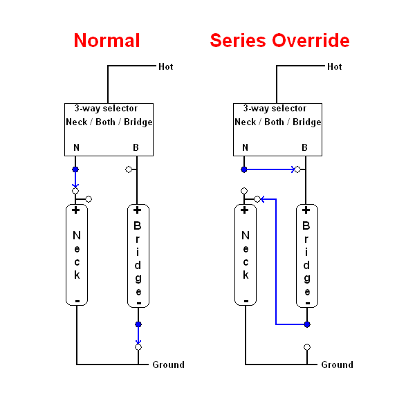 Does this make sense to you? And if not, then ask your questions - we're here to help! sumgai |
|
|
|
Post by sumgai on Sept 6, 2019 23:14:34 GMT -5
In fact, on 51-57 P basses (including the earlier Telecaster Bass), the mute itself was glued inside of the bridge cover. When you removed the cover, so went the mute. However, if you wanted the cover (for looks?), you could rip out the mute, if you so desired.
From a 1952 P-Bass:

On Jaguars (and a very few other Fender models, most of them extinct and forgotten), the mute was mounted under the Bridge itself, and was selectable - on or off. If you were used to palm muting, but wanted to strum with the pick over some other area of the strings, you could flip the mute on for effect.
Here's an image:

That chrome piece that's not part of the bridge itself is mounted to the body, directly centered under the bridge. Like a Strat's bridge, it pivots on screws, and a spring holds the metal piece in one postion or the other - it has sort of a snap feel. Obviously, you push down on one side of the metal piece to make the foam strip contact the strings, and push on the other side to break the contact.
But we're talking about basses, so just ignore what I said.
HTH
sumgai
|
|
|
|
Post by sumgai on Sept 6, 2019 22:46:20 GMT -5
Gang, The Staff and I are pleased to announce that thetragichero has been promoted to Moderator. So far, we've assigned him to overseeing the Gallery, Lutherie and Effects boards. We may ask him to take on others, if he doesn't protest too much. trag, aboord! sumgai |
|
|
|
Post by sumgai on Sept 5, 2019 10:10:51 GMT -5
frets, Don't thank me, I was only the messenger. Thank John for taking the time to develop this idea from not much more than scraps of conversations he particpated in, over the years. Glad it's working out for you, but again - don't hesitate to ask questions. Either here in this thread, or start another that might be more specific... it's all good! sumgai |
|
|
|
Post by sumgai on Sept 4, 2019 11:05:45 GMT -5
.... i haven't been banned yet! No, but we're actively working on it! 
Congrats, man, you've put paid to the account of "Anyone can do it, if they just keep trying". The Staff will soon convene to consider how to mail you your Gold Star!
|
|
|
|
Post by sumgai on Sept 3, 2019 22:37:19 GMT -5
frets, ange threw at you a lot of beginner's AC theory, so don't feel ashamed that some of it didn't stick the first time around. I have a couple of web pages bookmarked in my folder, but first, I wanna see if this link does any good for you. It goes to a speradsheet made by our very own JohnH, and he's been improving it for more than 10 years now - it's meant for guitarists specifically, yet it's easy to use, nearly all of the instructions are right on the page(s) you are intersted in. Try this on for size, and see if it answers your questions. If not, let me/us know, right back here in this thread. JohnH's Guitar Frequency Response CalculatorGood luck! sumgai |
|
|
|
Post by sumgai on Sept 3, 2019 18:16:33 GMT -5
.... While not quite feeding from the bottom, they get to make something of the experience not granted to the six strings. Looks like someone's been ignoring Charlie Hunter..... Yeah, you counted the number of tuners correctly - that's three bass strings and 5 guitar strings. While C.H. is primarily a jazz player, he can whip out some mean blues on occasion. sumgai |
|
|
|
Post by sumgai on Sept 2, 2019 23:49:12 GMT -5
Throughout the years (nearly 60 of 'em!), the Jazz Bass has had several wiring incarnations. And when the P-Jazz is thrown into the mix, we get even more options to choose from. But in my experience, the J-Bass has always had parallel wiring for one reason - two bass pickups in series will get awful muddy, and in a hot hurry! The very reason the J-Bass was created, and given that second pickup, was to give it some snap, some pizazz that single-pickup basses of the time simply did not have.
I've heard and played many a bass, and I've never been disappointed with the J-Bass's ability to snap, thump, growl, rumble, or just about any variation in between. But then again, all of that capability is dependent somewhat on the amp, and much more so on the speaker setup. Without a good cabinet, equipped with good matching speakers, you won't get diddly out of the box, no matter how much you spent for that bass guitar.
You want thump? How much weight can you cart into and back out of a gig? (Alternate question: how much beer have you budgeted for your roadies?) Because you want an Ampeg SVT-410HLF, new or used. When paired with a high-powered head, that sucker will make an audience puke at 75 feet! With a Jazz Bass - ask me how I know! (Fun fact: the HLF suffix means it has a horn, so it can do some screaming solos as well.)
Mine weighed about 110 pounds! Couldn't use it when I went over to the dark side (all MIDI gear), so I traded it in at GC for a new GR-55. My back loves me!
HTH
sumgai
|
|
|
|
Post by sumgai on Sept 2, 2019 23:21:49 GMT -5
..... connecting a resistor and capacitor as described will form an impedance that is the parallel combination of the frequency-independent resistance R and the frequency-dependent reactance 1 / 2piFC which is the product of these two factors divided by their sum Fixed the forgotten inversion. The formulas is spoken as "one over two times pi times frequency times capacitance". Without that inversion, higher frequencies would have a more difficult time getting through a cap, instead of having an easier time, as we see in the real world.
One question though: Is this question about Tone controls (in the form of a standard treble roll-off), or treble-bleed circuits incorporated with Volume controls?
sumgai
|
|
|
|
Post by sumgai on Sept 1, 2019 18:19:38 GMT -5
Well, that certainly gob-smacked me upside the head!! I had a paisley Tele while I was in Germany, Lo these many decades ago. It had been pretty badly beaten up by a previous owner, so I sanded it down to bare wood and did a natural finish. In the process, I didn't find any "fabric", but it was messy to remove, as in I think it was a special decal material that was somehow made to stay in place while being clear-coated. A normal water-based decal, like we often use for headstock names, that would've been easy to remove - not the one I got my hands on, way back when. But you know, in this day and age, I'd almost bet that a guitar body could go "under the pen" (as in, a light pen), and a laser could literally shoot at a refractive surface material - where it didn't hit, the material remained in place. Sort of like etching a printed circuit board. And it's not a very large stretch of the imagination to see that they could do color in the same manner - it'd be only a matter of technology, and cost of all that versus doing it the old-school way (decal, etc.) IMHO, of course. sumgai |
|
|
|
Post by sumgai on Aug 29, 2019 10:25:57 GMT -5
John,
I think we're getting a bit mixed up here - the inductance of a coil (in ancient times, it was called an inductor) is fairly immutable. However, the inductive reactance is what changes with frequency... and that leads to impedance being the deciding factor in calculating the effect of a either a cap or a coil on what frequencies will be heard at the output.
(For those who just tuned in, we can simplify the term Impedance to mean that it is essentially nothing more than resistance to an AC signal. Both are shown in units of Ohms. Of course there's more to it, a lot more, but for us guitar modders, that's it in a nutshell.)
All,
Impedance is calculated as a product of frequency, DC resistance and inductive reactance. (Ditto for capacitors, but substitute capacitive reactance.) There are many, many websites out there with lots of info, some simple enough for the lay person, others that go way beyond a PHd-level thesis. As you go searching aboot, try not to get bogged down with those latter sites.
But yes, the impedance of one inductor will be doubled if another similarly-valued inductor is placed in series with it, and the overall impedance of two similar inductors in parallel will be half of the value of one inductor... or a quarter of the total in our series example. Knowing this, we can extrapolate that a series circuit will present a higher impedance to the following circuit (amp, pedal, etc.). But sadly for us as guitar players, is the fact that the cable's capacitive impedance will work with that higher inductive impedance to suppress the higher frequencies.. And of course, the opposite is true for a parallel setup, the higher frequencies won't be so severly depressed, so the signal will seem more pronounced, by comparison.
And for what it's worth, the overall volume level of two pups, as measured on laboratry instruments, will be less than one-half of decibel different between them. Not so easily demonstrated, unless one's workbench is populated with test equipment costing more than one's automobile. Remember, if the highs are missing, and you think the mids/lows have been emphasized by comparison, then your ears are (and in truth, your brain is) compensating for that differentiation. Since no two people hear the same thing in exactly the same way, it's a bit of a stretch to 'assume' that everyone gets the same results. (i.e. the old saw that goes "Series is louder".) I know I don't think that series is louder... in fact I think it's only "more muddy" because the highs are missing, which leads me to believe that there's no clarity, something I consider important in a sound/tone.
But that's just me. As usual, YMMV. 
Final note: If you're really worried aboot your Mojo Tone, then you'll understand why ChrisK and I have always said that the best cable is made out of RF. In other words, ditch the wire-and-rubber and get a radio! Your ears will thank you. Not to mention, there goes absolutely all of the hum you ever suffered - all of it!
That's my morning dump! 
HTH
sumgai
|
|
|
|
Post by sumgai on Aug 29, 2019 0:07:55 GMT -5
I think that someone was afraid of a future 'repeat' failure, and took steps to avoid any such. Meaning, the original cap (this or another one) came unsoldered, or otherwise unsecured, and caused him/her no small amount of grief. Not what I would've done, but then again, any port in a storm, eh?  Unless you see burn/scorch marks somewhere near by..... |
|
|
|
Post by sumgai on Aug 28, 2019 12:19:26 GMT -5
Today's Nut(z)Shell Theory:
In point of fact, "phase inversion (or reversal)" is dependent on the signal formed in two coils, but derived from one source - in this case, a vibrating string. Phase inversion between two pups that are not being excited by the same string is a non-starter. QED. (Focused fields have a drop-off ratio of the fourth power, hence any imagined overlap will be non-noticible outside of a laboratory.)
Parallel vs. Series. Different story here.
In a series relationship, the impedances will add (just like resistors), and the overall effect on tone will be to reduce the highs and emphasize the lows/mids. In a parallel lash-up, the opposite is true. When Leo first let the Telecaster Bass escape his factory, he put the pickups in series in order that the bass not be so piercing as to compete with the lead instruments. Not to mention, in those days, there were very few amplifiers/speaker boxes that could easily recreate the lower frequencies, so any help he could give them was a bonus... in his mind.
Times do change, eh? At least, according to Bob Dylan they do.
sumgai
|
|
|
|
Post by sumgai on Aug 28, 2019 11:49:33 GMT -5
trag,
Show me more images of that cap, from different angles... please.
sumgai
|
|
|
|
Post by sumgai on Aug 24, 2019 14:44:31 GMT -5
mark, Hi, and to The NutzHouse! Stupid question, I had to ask. If I use a 250k or 500k tone control potentiometer will the sound change? In most cases, yes, you can hear a difference - when the control is turned all the way up to 10. And critically important, only when there are no other influences involved that may make it hard(er) to tell the difference. By that I mean, no other sounds such as a band going full bore... that'll mask any differences for sure. Other components being changed while changing the pot will also skew your listening results, so watch out for that "gotcha". Even such a simple thing like changing strings will cause your ears to go "What the....". But in general, with the control set to 10, you'll get a brighter overall tone with a higher value pot. In essence, you can get the "sound" of a 250K pot while using a 500K pot simply by turning down the 500K unit to about 8 for a log taper pot (sometimes called an audio taper), or down to about 5 for a linear taper pot. Yes, you have it correct - you've chosen the wrong set of terminals to solder your wires onto. Simply put those wires on the opposite set of terminals, and you'll be good to go. HTH sumgai |
|
|
|
Post by sumgai on Aug 24, 2019 10:52:27 GMT -5
Maple with white or off-white dots looks nice on a white body. This neck has big, black, block markers, and that makes a lot of difference in what colors it can match up with.
sumgai
|
|
|
|
Post by sumgai on Aug 23, 2019 20:10:44 GMT -5
trag,
That off-white thing should have a rosewood/ebony fingerboard, with custom fret markers the same color as the body, and big enough to be noticed for what they are.
sumgai
|
|
|
|
Post by sumgai on Aug 23, 2019 15:25:10 GMT -5
trag, You do understand that your beautiful maple neck with black block markers belongs on a sunburst paint job, yes? White just doesn't cut it, IMHO. sumgai |
|


 IOW, you don't need to be an EE in order to come up with a working design that fulfills all of your needs/desires/fantasies. In fact, if you do a bit of research, you'll find the way more than half of all the boutique amp builders out there have no formal training in the electronic arts. Those that do have more than in inkling in how to design an amp, they're what I'd call the Gold Standard. But that's just my personal prejudice showing through, once again.

 to The NutzHouse!


