|
|
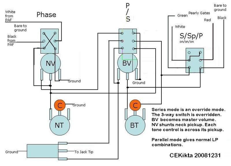
Post by ChrisK on Jan 10, 2009 23:46:09 GMT -5
Excellent project John. Yes, but care must be taken to limit the low frequency amp response as well. If the speaker is driven below the resonant port frequency, the speaker is no longer acoustically loaded and can easily be overdriven. This is the primary reason why ported guitar cabinets must not be used with a bass guitar. Now, in primarily open back cabinets (really big ports) there's not much acoustic loading anyway, but speaker death still occurs. And this, boys and girls, is why many bass cabs are closed back (acoustic suspension). There is no peaking (the peaking of the bass reflex cab and rock are ideal for each other), but the frequency response falls off gradually and the acoustic loading is relatively consistent. Many do. My Godin xtSA, Nashville Power Tele (which also has a hex pickup added), and Parker all do. For the drivers (speakers, BTW, they're both from Oz, John)); en.wikipedia.org/wiki/Thiele/SmallFor the enclosure; en.wikibooks.org/wiki/Engineering_Acoustics/Bass_Reflex_Enclosure_DesignBack in my Glass Audio/Speaker Builder days (when I still thought that I could hear - the loud music that I listened to was mostly classical and Led Zeppelin), I used to design custom enclosures. You know, that pedestrian Isobarik/D' Appolito stuff. Man, talk about a money pit.....I'm glad I can't hear anymore. IsobarikName from the original loudspeakers that first used the design. The bass driver sits at the front of a tunnel of identical shape, a second bass driver is at the rear of this. As both drivers move in unison, the front driver gets the impression the speaker cabinet is about six times larger than it actually is, resulting in that equivalent amount of bass performance. D' AppolitoA design that has mirrored drivers around a central tweeter. These drivers can be woofers only or woofers (outside drivers) and mid-ranges (drivers closest to tweeter). www.speakerbuilding.com/content/1105/02_drawing.jpgSome links; en.wikipedia.org/wiki/Loudspeakeren.wikipedia.org/wiki/Guitar_speakeren.wikipedia.org/wiki/Loudspeaker_enclosurewww.hometheaterhifi.com/features/technical-topics/how-a-hole-in-the-box-works.htmlwww.humblehomemadehifi.com/www.speakerbuilding.com/ |
|
|
|
Post by ChrisK on Jan 10, 2009 15:09:19 GMT -5
Simple is. Yeah, that's what makes it a tone circuit.  Again, simple is. Leo solved this over 50 years ago to save cap coin in the first Strat. The cap is shared in the leg to signal ground from both pots. This is where you'd place the switch. So, since we've been discussing exactly this concept most recently, I'm gonna say, "hey, pay attention." This one gives three cap values from two caps. Free "Woman Tone"If you look in The Demented TeleBlender, S2 puts two caps in sequential value order to realize three values. Now, if'n you take wolf's circuit posted by cyn1 and use a SP3T Center-OFF switch, you will have no cap in the middle position. 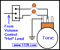 Wolf's site is a great resource for ideas and inspiration. www.1728.com/guitar.htmDon't be concerned that the pot is connected to signal ground and the switch is connected to the signal. (Your only clue is that series networks are not affected by the positional order of their linear components, and are also not affected by "gravity".)  Now, there will be some slight interaction between the pickups if both of their tone controls are turned down and only one is selected, since they will be sharing a common capacitor. If this is a problem (it might be a neat feature, what do I know), use a DPDT Center-OFF switch and two caps per section/pickup/tone pot. This cap sharing can also be easily done with a DP3T Center-ON (ON-ON-ON) switch, but the same interaction issue will exist. Since you prob'ly have the DP3T Center-ON (ON-ON-ON) switch, use this for reference. Fun With Toggles & Push-Pull Switches |
|
|
|
Post by ChrisK on Jan 9, 2009 19:14:35 GMT -5
Hmmm, so you still need to take things there to keep you occupied while you're there?  ;D ;D |
|
|
|
Post by ChrisK on Jan 9, 2009 19:04:11 GMT -5
I ordered a web special unfinished 2 piece swamp ash Tele body routed for two humbuckers with the forearm, tummy, and heel contours for $109. $109! Shipping to me on the "right" coast of the U.S. cost $20. So, it's a $129 body. Now, to be honest, I have about 5 builds in the oven and didn't need this, but did I mention that it was $109! 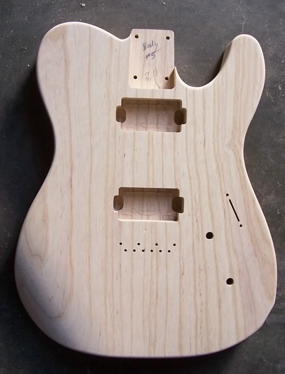 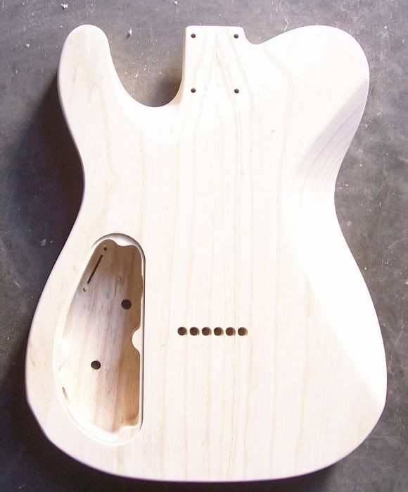 Check out USACG, they're guys that left Warmoth a while back and started their own shop. Their web special bodies are usually about $50 to $100 less than Warmoth. (Now, some of you might notice that I didn't say Warmoth. The guy there that so p  d me off isn't there anymore. However,.......) www.usacustomguitars.com/index.htmlwww.usacustomguitars.com/bodyspecials.aspwww.usacustomguitars.com/neckspecials.asp |
|
|
|
Post by ChrisK on Jan 9, 2009 17:31:58 GMT -5
Reciprocals can be confusing. One has to be religious about the units. For just two caps, the C1 * C2C1 + C2 method is the easiest. For 0.022 and 0.047, we'll use nanofarads as the consistent units. 22 * 47 = 22 + 47 1,034 = 14.9855 or 15 nanofarads 69 15 nF = 0.015 uF The equations for caps in series are the same as those for resistors or inductors in (non-inductive coupling) parallel. The equations for caps in parallel are the same as those for resistors or inductors in (non-inductive coupling) series (they just add). Some examples; 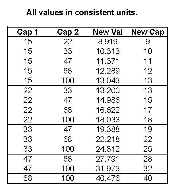 |
|
|
|
Post by ChrisK on Jan 9, 2009 1:22:23 GMT -5
Do you have some digital pics of the circuit board and ICs thereon?
|
|
|
|
Post by ChrisK on Jan 9, 2009 1:18:46 GMT -5
I originally used this idea in My "Proper" Telecopy a few years back. It's S2 in the schematic link. I used a DP3T ON-ON-ON so that the values were in sequential order (0.0015 uF, 0,0022 uF, and 0.047 uF). Actually, no. You converted the values to nF (nano Farads). Your answer should have been 14.98 or 15 nF 1/22 = 0.045454545454545454545454545454545 1/47 = 0.021276595744680851063829787234043 sum = 0.066731141199226305609284332688588 1/0.066731141199226305609284332688588 = 14.985507246376811594202898550725 1/22 + 1/47 =/= 1/67. 1/22 + 1/47 = 1/15'ish. As long as one minds the units scaling (uF, pF, or furlongs per forte night), it will always work always. 1/0.022 = 45.454545454545454545454545454545 1/0.047 = 21.276595744680851063829787234043 sum = 66.731141199226305609284332688588 1/66.731141199226305609284332688588 = 0.014985507246376811594202898550725 Consistent units. As newey indicated, it's 1/(1/C1 + 1/C2 + 1/Cn) for any number of capacitors in series. Or, for just two, it's C1 * C2C1 + C2 |
|
|
|
Post by ChrisK on Jan 8, 2009 19:01:05 GMT -5
tedfixxIf one connects two tone caps this way, and uses a SP3T (SPDT Center-OFF) switch, one gets 3 cap values. 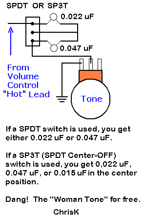 Any cap values can be used, the center (series) position value will be 1/[1/C1 + 1/C2] or C1 * C2C1 + C2 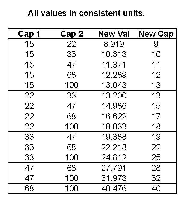
|
|
|
|
Post by ChrisK on Jan 8, 2009 18:55:58 GMT -5
Yeah, but if'n you do it this way; 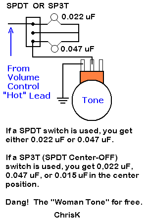 you get 3 (count 'em 3) cap values. |
|
|
|
Post by ChrisK on Jan 8, 2009 17:03:00 GMT -5
Nobody was off at all! 100 uA, 0.1 Ma, or 0.0001 A is the same exact thing in an absolute sort of way.  50 uW, or 0.05 mW or 0.000,05 W is the same thing as 0.000,000,05 KW or 0.000,000,000,05 MW. To be really safe we should go with 0.000,000,000,1 MW resistors. |
|
|
|
Post by ChrisK on Jan 8, 2009 11:56:18 GMT -5
I don't know, how hard do you play?   ;D ;D It's even lower if'n you measure it in amps....... ;D ;D A typical single coil pickup has an internal resistance of aboot 5 K Ohms. As per the maximum power transfer theorem, the maximum power is, uh, transfered when the load impedance equals the output impedance. This would be at 5 K Ohms. Using the 1 VAC example, this would result in 0.5 VAC across the external load of 5 K Ohms, which results in 0.5/5,000 or 100 uA (0.0001 A, or in newey's case 0.1 Ma  ). This results in a power dissipation of 50 uW (0.00005 W). This is aboot the maximum worst case that can generated by passive electric guitar circuitry. The reason why we use 1/4 or 1/8 watt components is that we tend to lose sight of those with much smaller ratings once we put them down (somewhere, dang it).   'Tain't much, aboot the magnitude of a bee's sneeze. |
|
|
|
Post by ChrisK on Jan 7, 2009 20:41:59 GMT -5
Hmmm, do you actually have a rack?
|
|
|
|
Post by ChrisK on Jan 7, 2009 20:40:27 GMT -5
Your homework assignment is to find and post a schematic diagram for discussion reference.  |
|
|
|
Post by ChrisK on Jan 7, 2009 20:36:09 GMT -5
Regarding it as reference point, yes, but really, no. "The DC resistance of a pickup tells you as much about a pickup's tone and output as the shoe size tells you about a person's intelligence!" Bill Lawrence  The inductance of the pickup structure (all of them in series) will likely be much less than a guitar pickup since all of the coil(s) turns are not on the same coil and hence, are not part of the same integral inductor (inductance is related to the number of turns ^2). Conversely, the inter-winding capacitance may be quite different as well. Does each coil have a ferrous core? Maybe a delay-on gate circuit might help since this may be attack-related. Is there an issue with the far end (or struck end) of the tone bars/keys having too much (or not enough) travel when being struck? Is it an issue of the felt/foam padding under each tone bar/key? Also, of the padding on top of each tone bar/key (under the fastening screw head)? The "resistor" is in effect in parallel with the amp input. You may or may not need this. Adding the resistor will limit the harmonics produced, but this type of instrument may be more fundamental in nature that a guitar ("fundamentally", most instruments sound like a flute except for the envelope). The pickup is an AC generator in series with its inductive reactance, its resistance and this structure is driving its inter-winding capacitance to signal ground. It's a series LCR circuit. The low-cut cap is in series with the signal from the pickup going to the resistor going to signal ground, and the output jack tip terminal. In essence, the cap is a frequency dependent capacitive reactance that forms a complex (plane) voltage divider with the generator and its series inductive reactance and resistance, driving the amp and resistor as a load to signal ground. Since the pickup is really 30 individual pickups with 1/30 the number of turns of a Tele pickup, we might assume that the inductance is much less. If the structure was identical (which it is not), it would 30^2 or 900 times less. As a WAG, let’s guess that if a typical Tele pickup was 4 henries (it’s not, but it’s an average of many), we might surmise that it could (not would) be 5 to 20 mH. If we picked 20 mH, the series total would be 600 mH. This is the design model for a single series low-cut capacitor. The pickup inductance is set to 600 mH, its series resistance to 4300 Ohms, and the inter-winding capacitance to 50 pF. The cable capacitance is set to 400 pF and the amp input resistance to 500 K Ohms. The “resistor”, which in this model is in direct parallel with the amp input resistance, is set to 200 K Ohms. 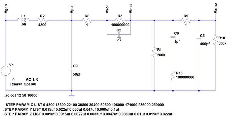 For a series capacitor range of 0.001uf, 0.0015uf, 0.0022uf, 0.0033uf, 0.0047uf, 0.0068uf, 0.01uf, 0.015uf, and 0.022uf, the following curves result. Ignore the dashed curves, as these are phase information which will just confuse me. The larger the capacitance, the less the attenuation. The vertical dashed grid lines from 50 Hz to 500 Hz are 50 Hz each. The peaking beyond 5 Khz is related to the series LCR circuit formed by the cable capacitance and my bad guesses as to component values, and therefore out of scope for this discussion.  Note that the response results in less attenuation than JohnH indicated, again from the component interaction in a passive (lossy) circuit. 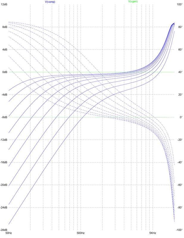 This is the design model for a dual series low-cut capacitor. The pickup inductance is set to 600 mH, its series resistance to 4300 Ohms, and the inter-winding capacitance to 50 pF. The cable capacitance is set to 400 pF and the amp input resistance to 500 K Ohms. The “resistor”, which in this model is NOT in direct parallel with the amp input resistance, is set to 200 K Ohms. The amp input resistance forms the second pole’s “resistor”. 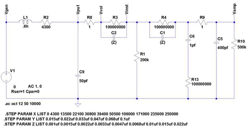 For a series capacitor range of 0.001uf, 0.0015uf, 0.0022uf, 0.0033uf, 0.0047uf, 0.0068uf, 0.01uf, 0.015uf, and 0.022uf, the following curves result. Note that the response does improve somewhat with a two-pole filter. 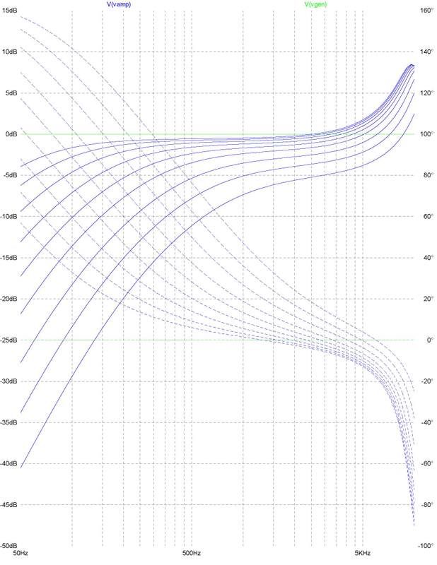 Anyway, this exercise will show the general response effect of various series caps in a SWAG circuit estimate. |
|
|
|
Post by ChrisK on Jan 6, 2009 12:09:56 GMT -5
Do you know the electrical specifications of this pickup (resistance, inductance, and inter-winding capacitance)? Do you have a manufacturer's specification sheet? "Everything" is a strong word. "Everything below a cutoff frequency of 200hz" indicates an absolute stop band, which is not really possible with passive components. Yes, and maybe. This one is easy; use a 1/4 w carbon or metal film resistor. No one can give you the absolute values without knowing the resistance, inductance, and inter-winding capacitance of the pickup, as well as all of the other elements in the passive signal chain including the instrument volume and tone controls (if applicable), the cable capacitance, and certainly the input characteristics of the amplifier (impedance, which needs to include the input resistance and capacitance). All of these components make up the passive circuit, in which all components affect each other toward the overall response. A standard single-pole RC filter will have a response curve of 6 dB per octave. Two in series will effect a 12 dB per octave response curve, except that, since these are interacting passive components, they really won't. Also, passive filters only reduce frequencies (we're not going to discuss the series LCR circuit here) so there is an insertion loss that will reduce the output signal. OK, here's the reality part; since ALL of the components in this passive circuit interact, stating any absolute values for you would be BS. If you can't post the specific component values for the pickup, amp, cable, and all other intertwined passive components in this passive circuit, I would suggest that you put together a test filter using a mix of capacitors and pots. This can reside between the output jack on the instrument and the input jack on the amp. Until I know some of the characteristics of the components, I can't give truly meaningful values to start with. I might start with 0.001 uF thru 0.01 uF and a 500K pot. Here is a guitar schematic that has both high-cut and low-cut tone controls. Now, knowing that this pickup is like a Telecaster pickup (which pickup, please), we could make some assumptions about your pickup. If we knew the amp model we could make some assumptions about this as well as the input cable (a 300 pF and up capacitor). Based on this, some pSpice (freeware versions available) models could be used to plot the probable frequency response curves for various configurations. This would give us some component values for testing. Guitar Electronics Modeling - pSpiceThis is not likely the simple answer that you hoped for. A simple fast way to reduce the low frequencies is to use a graphic equalizer pedal between the instrument and amp. These have both boost and cut functions in specific frequency bands, usually of +/-12 to +/- 15 dB. |
|
|
|
Post by ChrisK on Jan 6, 2009 0:22:21 GMT -5
Yep.
The two outside terminals are connected to the ends of the resistive element which can be within +/- 20% to +/- 30% of the nominal value. This value is the rated resistance value for a pot. The middle terminal is the wiper and the sum of the readings from it to each end terminal will be very close to what is read across the end terminals.
|
|
|
|
Post by ChrisK on Jan 6, 2009 0:12:52 GMT -5
So, the question arises again; are we worried about fake counterfeits or counterfeit fakes?
|
|
|
|
Post by ChrisK on Jan 3, 2009 21:38:46 GMT -5
Yeah, that there beautiful '57 Goldtop!  Holy mother of cow pies, that's a mighty big microwave.  Baskin-Robbins only has 31 flavors of ice cream. I've had that many Strats over the years (well, that many Fenders). Only if'n they gets a good beating as they pass thru Mexico (which is way much less that improbable). Fender model numbers 013xxxx-xxx are Mexican in origin. These all have the skinny neck (1.650"). Now, that's marketing, selling Mexican Fenders for the price of a U.S. made Standard Strat. If you beat on your guitar, it goes down in value, if it's pre-beaten, it goes up. To be fair, they do have a nitrocellulose-lacquer finish, and are supercharged* with Tex-Mex™ pickups and 6105 frets. I care about the finish and 6105's are my favorite fret size, although every U.S. Highway 1 that I've played (nitrocellulose-lacquer finish) seemed dull in tone. *" supercharged" is a marketing term that means absolutely nothing and therefor incurs no liability for anything including nothing. This statement may include forward-looking statements which should not be interpreted to mean anything including nothing. This statement may also include backward-looking statements which should be interpreted to mean nothing including everything. Furthermore, this statement may be interpreted by some as being somewhat irreverent toward those engaged in the legal profession** and should not be construed to be an apology in any stretch of anyone's imagination, but if it is construed to be such, then it is unknowingly denied. **Except for you, and you know who you are.  |
|
|
|
Post by ChrisK on Jan 3, 2009 21:32:06 GMT -5
What makes folk think that the next generations will be interested in the toys of OUR youth?   After all, things are only worth what someone is willing to pay for it. (Pssst, it's all an insurance company premium inflation conspiracy.)  |
|
|
|
Post by ChrisK on Jan 3, 2009 21:23:43 GMT -5
Apparently, a beautiful '57 Goldtop!  |
|
|
|
Post by ChrisK on Jan 3, 2009 21:18:20 GMT -5
To match the toggle switch. To match the control layout. Actually, to match the natural motion of the strumming hand. You do now, it's hysterical in nature. Huh? I presume that the volume controls are in-line and closest to the strings. I presume that the tone controls are nearest the lower bout. Do you also reverse the 3-way switch? Does forward (neck-ward) now select the bridge, and aft-ward (bridge-ward) now select the neck? If so, call Gibson, you're their kind of thinker. ;D ;D ;D (Oh, this isn't one of those Oz things is it?)  |
|
|
|
Post by ChrisK on Jan 3, 2009 1:39:45 GMT -5
In the U.S., firearm suppressers are regulated and licensed, and generally frowned upon.
In Finland (I believe) one is required to use one to avoid disturbing the neighbors.
I always thought that they should be used to avoid disturbing the police.
Go figure.
|
|
|
|
Post by ChrisK on Jan 1, 2009 1:15:39 GMT -5
What's wrong with you people?
So you can't sleep, quit typing and go wire something already.
|
|
|
|
Post by ChrisK on Jan 1, 2009 1:10:00 GMT -5
Do tell. Hopefully it was an ARP2500 for a pittance. I spent my late teens trying to realize reliable exponential/log analog circuits to do tracking analog synth oscillators. I still have many samples of log/anti-log ICs. Now I just use a digital one that pretends to be analog (in the operator interface).  |
|
|
|
Post by ChrisK on Jan 1, 2009 0:42:04 GMT -5
I remember when I had that one too. One third of a century and half way done (with a normal career). That depends on how you look at things ( astrophenomically speaking). Celestial and Classical Mechanics rule, except when n(o)-body can solve it. Remember, everything is either physics, religion, or marketing.  |
|
|
|
Post by ChrisK on Jan 1, 2009 0:31:39 GMT -5
THANK GOD THAT YOURE DOING BETTER ITS A GOOD THING THAT OTHERS DONT HAVE SIMILAR TEXTING PROBLEMS AS ID BE HAVING TO SPEND TIME HELPING THEM THRU REHAB ALSO IM GLAD TO BE DOING BETTER MYSELF TO IMPROVE MY STEAD IN LIFE WHEN YOU GET LEMONS JUST MAKE LEMONADE GIVES ME HEARTBURN CAN BE CONFUSED WITH A HEART ATTACK LIFE WITH GUSTO.
('.'.'.') ;D ;D
|
|
|
|
Post by ChrisK on Jan 1, 2009 0:24:03 GMT -5
|
|
|
|
Post by ChrisK on Dec 31, 2008 22:05:00 GMT -5
/no
|
|
|
|
Post by ChrisK on Dec 31, 2008 21:55:37 GMT -5
Yep.
And you've all heard the one aboot the dyslexic rabbi (Yo)?
One of the things that I got for Christmas was the Seymour Duncan pickup DVD. I've had their 3 CD pickup set for several years and have listened to it often.
|
|
|
|
Post by ChrisK on Dec 31, 2008 21:44:42 GMT -5
Happy New Year to all, both to those over the threshold and those yet to cross.
I have to stay inside since the automatic weapons fire is aboot to start here (in a couple of hours).
|
|





 d me off isn't there anymore. However,.......)


 ;D ;D
;D ;D


